X20 system modules • Analog input modules • X20AI1744, X20AI1744-3
X20 system User's Manual 3.10
131
Product ID
X20AI1744
X20AI1744-3
Mechanical characteristics
Note
Order 1x X20TB12 terminal block separately
Order 1x X20BM11 bus module separately
Spacing
12.5
+0.2
mm
Table 19: X20AI1744, X20AI1744-3 - Technical data
1)
Depends on the full-bridge strain gauge used
2)
With 6-wire connections, line compensation does not function. (See section "Connection examples")
3)
The maximum current of 90 mA is permitted up to an operating temperature of 45°C.
4.3.2.4 Status LEDs
The status LEDs are identical on the X20AI1744 and X20AI1744- 3 modules.
Image
LED
Color
Status
Description
Off
No power to module
Single flash
Reset mode
Double flash
Boot mode (during firmware update)
Blinking
Preoperational mode
r
Green
On
RUN mode
Off
Module supply not connected or everything OK
e
Red
On
Error or reset status
Off
Possible causes:
•
Open line
•
Sensor is unplugged
•
Converter is busy
1
Green
On
Analog/digital converter running, value OK
Table 20: Status LEDs
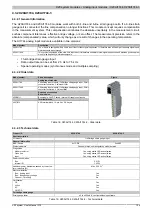
4.3.2.5 Pinout
The pinouts are identical on the X20AI1744 and X20AI1744- 3 modules.
Strain gauge VCC
Strain gauge VCC
Strain gauge VCC
Strain gauge VCC
X
20
A
I 1
74
4
Strain gauge GND
Strain gauge GND
Strain gauge GND
Strain gauge GND
r
e
1
Input +
Input +
Input -
Input -
Figure 48: Pinout


