X20 system modules • Digital output modules • X20DOF322
1310
X20 system User's Manual 3.10
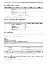
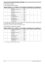
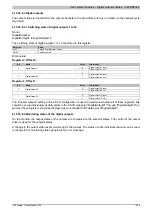
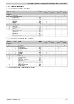
4.15.30.9.4.1 Status of digital outputs 1 to 16
Name:
StatusDigitalOutput or
StatusDigitalOutput01 to StatusDigitalOutput16
The status of digital outputs 1 to 16 is mapped in this register.
Data type
Value
UINT
Packed "StatusDigitalOutput" values
USINT
See bit structure
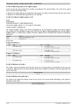
Bit structure:
Register 30, Offset 1:
Bit
Name
Value
Description
0
Channel 01: No error
0
StatusDigitalOutput01
1
Channel 01: Short circuit or overload
...
...
0
Channel 08: No error
7
StatusDigitalOutput08
1
Channel 08: Short circuit or overload
Register 31, Offset 2:
Bit
Name
Value
Information
0
Channel 09: No error
0
StatusDigitalOutput09
1
Channel 09: Short circuit or overload
...
...
0
Channel 16: No error
7
StatusDigitalOutput16
1
Channel 16: Short circuit or overload
The "packed outputs" setting in the AS I/O configuration is used to determine whether all of these registers' bits
should be set up individually as data points in the AS I/O mapping ("StatusDigitalOutput01" through "StatusDigi-
talOutput16") or whether these registers should be displayed as an individual UINT data point ("StatusDigitalOut-
put").
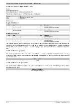
4.15.30.9.5 Minimum cycle time
The minimum cycle time defines how far the bus cycle can be reduced without communication errors occurring.
It should be noted that very fast cycles decrease the idle time available for handling monitoring, diagnostics and
acyclic commands.
Minimum cycle time
100 μs
4.15.30.9.6 Minimum I/O update time
The minimum I/O update time defines how far the bus cycle can be reduced while still allowing an I/O update to
take place in each cycle.
Minimum I/O update time
Equal to the minimum cycle time

