X20 system modules • Counter modules • X20DC137A
X20 system User's Manual 3.10
739
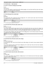
4.11.9.8.3.4 Signal channels for triggering latch procedure
Name:
CfO_LatchComparator
This register defines the signal channels and their level for triggering the latch procedure.
•
This mainly configures which channels are linked to generate the latch event. All three signals from the
encoder and digital input 1 can be used for the "AND" operation.
•
The "active voltage level" needed for the latch procedure can now be used according to the physical signals.
Data type
Value
USINT
See bit structure.
Bit structure:
Bit
Name
Value
Information
0
Low
0
Defines signal level for encoder signal A
1
High
0
Low
1
Defines signal level for encoder signal B
1
High
0
Low
2
Defines signal level for encoder signal R
1
High
0
Low
3
Defines signal level for digital input 1
1
High
0
Disabled
4
Use encoder signal A to trigger latch procedure
1
Latch function linked to encoder signal A
0
Disabled
5
Use encoder signal B to trigger latch procedure
1
Latch function linked to encoder signal B
0
Disabled
6
Use encoder signal R to trigger latch procedure
1
Latch function linked to encoder signal R
0
Disabled
7
Use digital input 1 to trigger latch procedure
1
Latch function linked to digital input 1
4.11.9.8.3.5 Physical configuration
The following registers must be set to the specified constant value for correct physical configuration:
Constant register "CfO_SIframeGenID"
Name:
CfO_SIframeGenID
Data type
Value
Information
USINT
9
Only default in the bus controller module
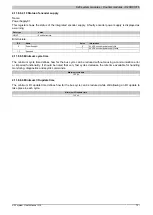
Constant register "CfO_SystemCycleTime"
Name:
CfO_SystemCycleTime
Data type
Value
Information
UINT
800
Only default in the bus controller module
Constant register "CfO_PhyIOConfigCh01"
Name:
CfO_PhyIOConfigCh01
Data type
Value
Information
USINT
0
Only default in the bus controller module
Constant register "CfO_PhyIOConfigCh02"
Name:
CfO_PhyIOConfigCh02
Data type
Value
Information
USINT
0
Only default in the bus controller module


