X20 system modules • Analog output modules • X20AO4635
500
X20 system User's Manual 3.10
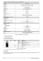
4.4.10.5 Pinout
Each channel can be configured for either current or voltage signals. The type of signal is also determined by the
connection terminals used.
AO + 1 I
AO + 1 U
AO - 1 U/I
AO + 2 I
AO + 2 U
AO - 2 U/I
1
X
20
A
O
4
63
5
2
AO + 3 I
AO + 3 U
AO - 3 U/I
AO + 4 I
AO + 4 U
AO - 4 U/I
3 4
r
e
Figure 196: Pinout
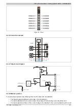
4.4.10.6 Connection example
GND
+24 VDC
GND
+24 VDC
AO
+
+
Voltage
Current
Lo
ad
Lo
ad
Lo
ad
Lo
ad
4.4.10.7 Output circuit diagram
AO + x I
AO + x U
AO - x U/I
Enable relay
Reset
D/A
Conversion
Output value
I/O status
LED (orange)
Figure 197: Output circuit diagram

