Coated modules • Bus controllers System modules • X20cPS9400
2526
X20 system User's Manual 3.10
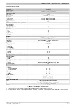
Product ID
X20cPS9400
Reverse polarity protection
Yes
Bus controller / X2X Link supply output
Nominal output power
7.0 W
Parallel operation
Yes
2)
Redundant operation
Yes
Overload behavior
Short circuit / temporary overload protection
Input I/O supply
Input voltage
24 VDC -15% / +20%
Fuse
Required line fuse: Max. 10 A, slow-blow
Reverse polarity protection
No
Output I/O supply
Rated output voltage
24 VDC
Behavior if a short circuit occurs
Required line fuse
Permitted contact load
10.0 A
Interfaces
Service interface
Signal
RS232
Design
Connection made using 12-pin X20TB12 terminal block
Max. transfer rate
115.2 kbit/s
Operating conditions
Mounting orientation
Horizontal
Yes
Vertical
Yes
Installation at elevations above sea level
0 to 2000 m
No limitations
>2000 m
Reduction of ambient temperature by 0.5°C per 100 m
EN 60529 protection
IP20
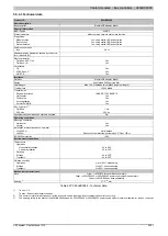
Environmental conditions
Temperature
Operation
Horizontal installation
-25 to 60°C
Vertical installation
-25 to 50°C
Derating
See section "Derating"
Storage
-40 to 85°C
Transport
-40 to 85°C
Relative humidity
Operation
Up to 100%, condensing
Storage
5 to 95%, non-condensing
Transport
5 to 95%, non-condensing
Mechanical characteristics
Note
Order 1x X20TB12 terminal block separately
Order 1x X20cBB8x bus base separately
Spacing
12.5
+0.2
mm
Table 931: X20cPS9400 - Technical data
1)
The specified values are maximum values. The exact calculation is also available for download as a data sheet with the other module documentation on
the B&R homepage.
2)
In parallel operation, only 75% of the rated power can be assumed. It is important to make sure that all power supplies operating in parallel are switched
on and off at the same time.


