X20 system modules • Digital input modules • X20DI4371
968
X20 system User's Manual 3.10
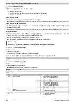
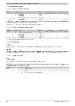
4.13.6.9.5.2 Resets the counter registers
Name:
ResetCounter01 to ResetCounter04
Using these data points, the corresponding counter registers can be reset to 0.
Data type
Value
USINT
See bit structure.
Bit structure:
Bit
Name
Value
Information
0
No change
0
ResetCounter01
1
Counter register 1 is reset
...
...
0
No change
3
ResetCounter04
1
Counter register 4 is reset
Information:
A counter is only reset if a positive edge is detected on the reset bit.
A continually set reset bit does not prevent counting in the counter register.
4.13.6.9.5.3 Configuration of the edges
Name:
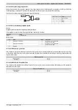
ConfigOutput02
This register is used to configure which event will be assessed on the channel input for the respective counter.
Data type
Value
USINT
See bit structure.
Bit structure:
Bit
Name
Value
Information
0
Event is not counted
0
Rising edge on input 1
1
Event increments Counter01
...
...
0
Event is not counted
3
Rising edge on input 4
1
Event increments Counter04
0
Event is not counted
4
Falling edge on input 1
1
Event increments Counter01
...
...
0
Event is not counted
7
Falling edge on input 4
1
Event increments Counter04
4.13.6.9.6 Minimum cycle time
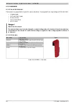
The minimum cycle time defines how far the bus cycle can be reduced without communication errors occurring.
It should be noted that very fast cycles decrease the idle time available for handling monitoring, diagnostics and
acyclic commands.
Minimum cycle time
Without filtering
100 μs
With filtering
150 μs
4.13.6.9.7 Minimum I/O update time
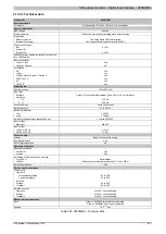
The minimum I/O update time defines how far the bus cycle can be reduced while still allowing an I/O update to
take place in each cycle.
Minimum I/O update time
Without filtering
100 μs
With filtering
200 μs

