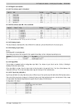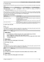
X20 system modules • Analog input modules • X20AI4222
260
X20 system User's Manual 3.10
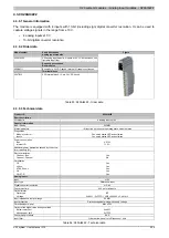
Product ID
X20AI4222
Max. error at 25°C
Gain
0.08%
2)
Offset
0.015%
3)
Max. gain drift
0.006 %/°C
2)
Max. offset drift
0.002 %/°C
3)
Common-mode rejection
DC
70 dB
50 Hz
70 dB
Common-mode range
±12 V
Crosstalk between channels
-70 dB
Non-linearity
<0.025%
3)
Isolation voltage between channel and bus
500 V
eff
Operating conditions
Mounting orientation
Horizontal
Yes
Vertical
Yes
Installation at elevations above sea level
0 to 2000 m
No limitations
>2000 m
Reduction of ambient temperature by 0.5°C per 100 m
EN 60529 protection
IP20
Environmental conditions
Temperature
Operation
Horizontal installation
-25 to 60°C
Vertical installation
-25 to 50°C
Derating
-
Storage
-40 to 85°C
Transport
-40 to 85°C
Relative humidity
Operation
5 to 95%, non-condensing
Storage
5 to 95%, non-condensing
Transport
5 to 95%, non-condensing
Mechanical characteristics
Note
Order 1x X20TB12 terminal block separately
Order 1x X20BM11 bus module separately
Spacing
12.5
+0.2
mm
Table 54: X20AI4222 - Technical data
1)
To reduce power dissipation, B&R recommends bridging unused inputs on the terminals.
2)
Based on the current measured value.
3)
Based on the 20 V measurement range.
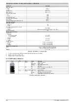
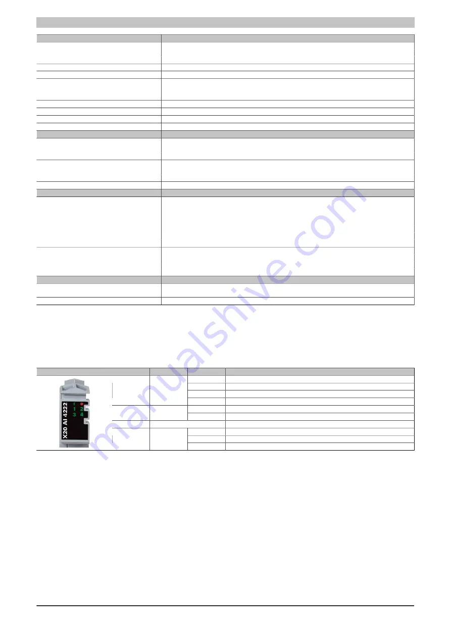
4.3.9.4 LED status indicators
Figure
LED
Color
Status
Description
Off
No power to module
Single flash
RESET mode
Blinking
PREOPERATIONAL mode
r
Green
On
RUN mode
Off
No power to module or everything OK
e
Red
On
Error or reset status
e + r
Red on / Green single flash
Invalid firmware
Off
Open line or sensor is disconnected
Blinking
Input signal overflow or underflow
1 - 4
Green
On
Analog/digital converter running, value OK
Table 55: LED status indicators


