X20 system modules • Digital input modules • X20DI4375
X20 system User's Manual 3.10
979
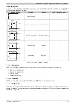
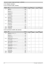
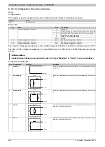
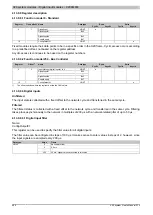
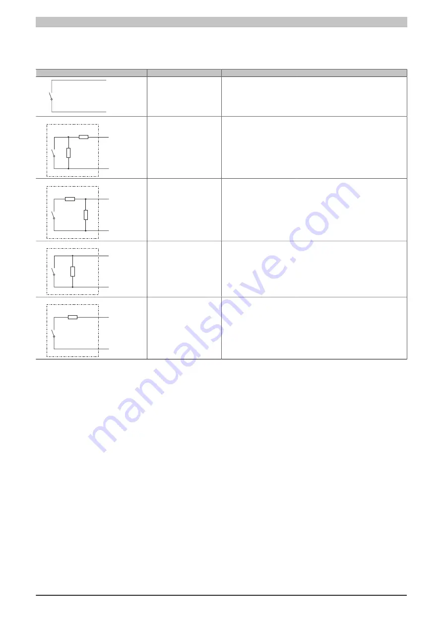
Connection options
To guarantee error-free functionality of the open circuit and short circuit detection, the +24 VDC sensor supply from
the module must absolutely be used.
Sensor connections
Description
Detection
Setting in configuration register
+24 V
Input x
Standard connection
-
0
R
S
R
P
Sensor
+24 V
Input x
Series and parallel resistance
Open circuit and short circuit
1
R
S
R
P
Sensor
+24 V
Input x
Parallel and series resistor
Open circuit and short circuit
2
R
P
Sensor
+24 V
Input x
Parallel resistance
Open line
3
R
S
Sensor
+24 V
Input x
Series resistor
Short circuit
4
Table 311: Connection options for sensor
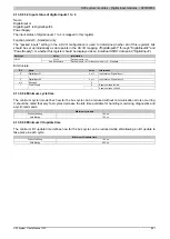
4.13.8.10 Error status
The following errors are detected by the module and can be evaluated separately for each channel:
•
Sensor line short circuit
•
Sensor line open circuit
•
Sensor supply
•
Other channel error
4.13.8.11 Timestamp
Each converted value is given a timestamp. The time of the last conversion can be read.
4.13.8.12 Configuration
The sensor connections and therefore the sensor monitoring are set in the configuration register. Sensor monitor-
ing and the settings in the configuration register are described in section 4.13.8.9 "Open circuit and short circuit

