X20 system modules • Analog input modules • X20AP31x1
348
X20 system User's Manual 3.10
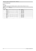
4.3.14.10.12 Module configuration
4.3.14.10.12.1 Analog mode register
Name:
ChanControl
Data type
Value
UINT
See bit structure
Bit structure:
Bit
Name
Value
Information
0
Disabled
0
Channel status LED for phase A
1
Enabled
1)
0
Disabled
1
Channel status LED for phase B
1
Enabled
1)
0
Disabled
2
Channel status LED for phase C
1
Enabled
1)
3
Reserved
0
0
Disabled
4
Neutral current monitor and status LED
1
Enabled
1)
0
Derived from the calculated value
1)
5
Neutral current status derived from the calculated or measured
value
1
Derived from the calculated value
0
Disabled
6
Conversion of energy register to kWh (internal register / 4096)
1
Enabled
0
Disabled
3)
, Current values = 0
7
Display current values despite power failure
2)
1
Enabled
0
Disabled
1)
, Current values = 0
8 - 15
Oversampling with prescaler
1 - 255
Enabled, Display current values despite power failure
1)
Standard in the bus controller function model
2)
When a power failure occurs, all current values are held at 0 by default.
3)
According to the power failure status of the individual phases, the following values are held at 0 by default.
•
Mains frequency, phase angle, power factor
•
Effective voltage and current values
•
Active, reactive and apparent power values
4.3.14.10.12.2 Analog minimum current for active current channel LED
Name:
IDispTh
Data type
Value
Information
UINT
100 to 65000
I RMS indicator threshold
The indicator threshold defines the RMS value of the current at which the status LED for the phase current is
illuminated. The default values vary from module to module and should be adjusted to the maximum primary
current. Suggestion: 1% of maximum value
Module
Indicator threshold
X20AP3111
200 mA
X20AP3121
500 mA
X20AP3131
500 mA
X20AP3161
500 mA


