X20 system modules • Motor controllers • X20SM1436
2024
X20 system User's Manual 3.10
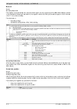
4.25.7.8 Input circuit diagram
Input x
GND
GND
VDR
Input status
I/O status
LED (green)
4.25.7.9 Output circuit diagram
LA
24 V - 39 V
HA
LA\
HA\
LB
HB
LB\
HB\
A
A\
B
B\
Current comparator A
Current comparator B
Motor
Controller
Motor
Controller
Voltage monitoring
24 V - 39 V
External supply
24 V - 39 V
External supply
Transil diode
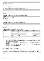
4.25.7.10 Overvoltage motor cutoff
The module supply voltage is continually monitored. Its status can be read. The error "Module power supply error"
occurs when the voltage is above or below the limits.
If the supply voltage on the module rises or falls outside the limit values (e.g. due to regeneration), then the motor
output is switched off.
The outputs are reactivated as soon as the supply voltage is back in the valid range and the error bit is reset.
Supply voltage limit values
Drive is switched off
Drive is switched back on
Lower limit
<18 V
>19.5 V
Upper limit
>50 V
<49 V

