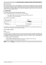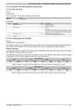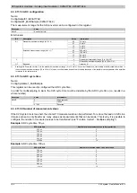
X20 system modules • Analog input modules • X20AI1744, X20AI1744-3
140
X20 system User's Manual 3.10
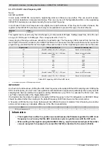
4.3.2.11.4.5 ADC clock frequency shift
Name:
AdcClkFreqShift01
In rare cases, X20AI1744 connected to neighboring slots can influence one another. This can result in tempo-
rary, minimal deviations in measurement values. This can only occur if the SigmaDelta ADCs on the neighboring
X20AI1744 modules are operated at exactly the same clock frequency.
In most cases, these clock frequencies vary slightly due to part variances. When they are the same however, this
register on the X20AI1744 provides a safe way for an application to prevent this type of mutual influence.
Data type
Value
SINT
-128 to 127
This register can be used to vary the clock frequency in increments of 200 ppm. Setting values from -50 to 50 cover
a range of -10000 ppm to 10000 ppm. This corresponds with -1% to 1%.
Values beyond this range will cause activation of a default mode. The frequency shift is derived from the from the
last 2 digits of the serial number by the X20AI1744 firmware. This saves time that would otherwise be needed for
programming, provided that the last two digits of the serial numbers on the neighboring modules are not the same
Register value
Frequency shift in ppm
Example of a sampling rate
1)
127
((SerialNo. modulo 100) - 50) * (-200) ppm
Based on the serial number
...
...
...
51
((SerialNo. modulo 100) - 50) * (-200) ppm
Based on the serial number
50
10000
505
49
9800
504.9
...
...
...
2
400
500.2
1
200
500.1
0
0
500
-1
-200
499.9
-2
-400
499.8
...
...
...
-50
-10000
495
-51
((SerialNo. modulo 100) - 50) * (-200) ppm
Based on the serial number
...
...
...
-128
((SerialNo. modulo 100) - 50) * (-200) ppm
Based on the serial number
Table 25: Frequency shift of the ADC clock
1)
Nominal sampling rate of 500 samples per second
IMPORTANT:
As shown in the table above, shifting the ADC clock frequency will equally shift the ADC sampling rate. Shifting the
ADC clock frequency too much can cause problems with disturbance suppression particularly when a very specific
sampling rate has been defined to suppress existing disturbances (e.g: 50 Hz to suppress the 50 Hz hum). Also
see "Filter characteristics of the Sigma-Delta ADC".
It's situations like this where the option to manually shift the frequency in the I/O configuration or ASIOACC library
should be utilized rather than relying on the default frequency shift that is based on the serial number.
A frequency shift like the one shown below would be sufficient to prevent modules from influencing one another
and would not cause any noticeable difference to the filter characteristics.
Slot
1
2
3
4
5
6
...
ADC clock frequency shift
0
2
-1
1
-2
0
...
Information:
•
This register has no effect in synchronous mode because the firmware regulates the ADC clock
frequency in such a way that the ADC conversion cycle is synchronous with the X2X cycle.
•
When writing to this register using the ASIOACC library, only the lowest value byte of the written
value is accepted. For example, the value 256 (=0x100) is identical to the value 0 (=0x00).


