X20 system modules • X20 CPUs • X20CP158x and X20CP358x
926
X20 system User's Manual 3.10
4.12.3.9 Slot for application memory
These CPUs require application memory in order to operate. The application memory is provided in the form of a
CompactFlash card. It is not included with the CPUs, but must be ordered separately as an accessory.
Information:
The CompactFlash card must not be removed during operation.
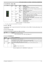
4.12.3.10 Operating mode switch
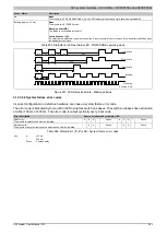
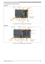
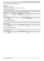
The operating mode switch is used to set the operating mode.
Figure 304: X20 CPUs - Operating mode switch
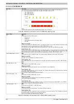
Switch position
Operating mode
Description
BOOT
BOOT
When the switch is in this position, the default B&R Automation Runtime (AR) system is started
and the runtime system can be installed via the online interface (B&R Automation Studio). User
flash memory is deleted only after the download begins.
RUN
RUN
RUN mode
DIAG
DIAGNOSE
Boots the CPU in diagnostic mode. Program sections in User RAM and User FlashPROM are
not initialized. After diagnostic mode, the CPU always boots with a cold restart.
Table 288: X20 CPUs - Operating modes
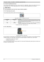
4.12.3.11 Reset button
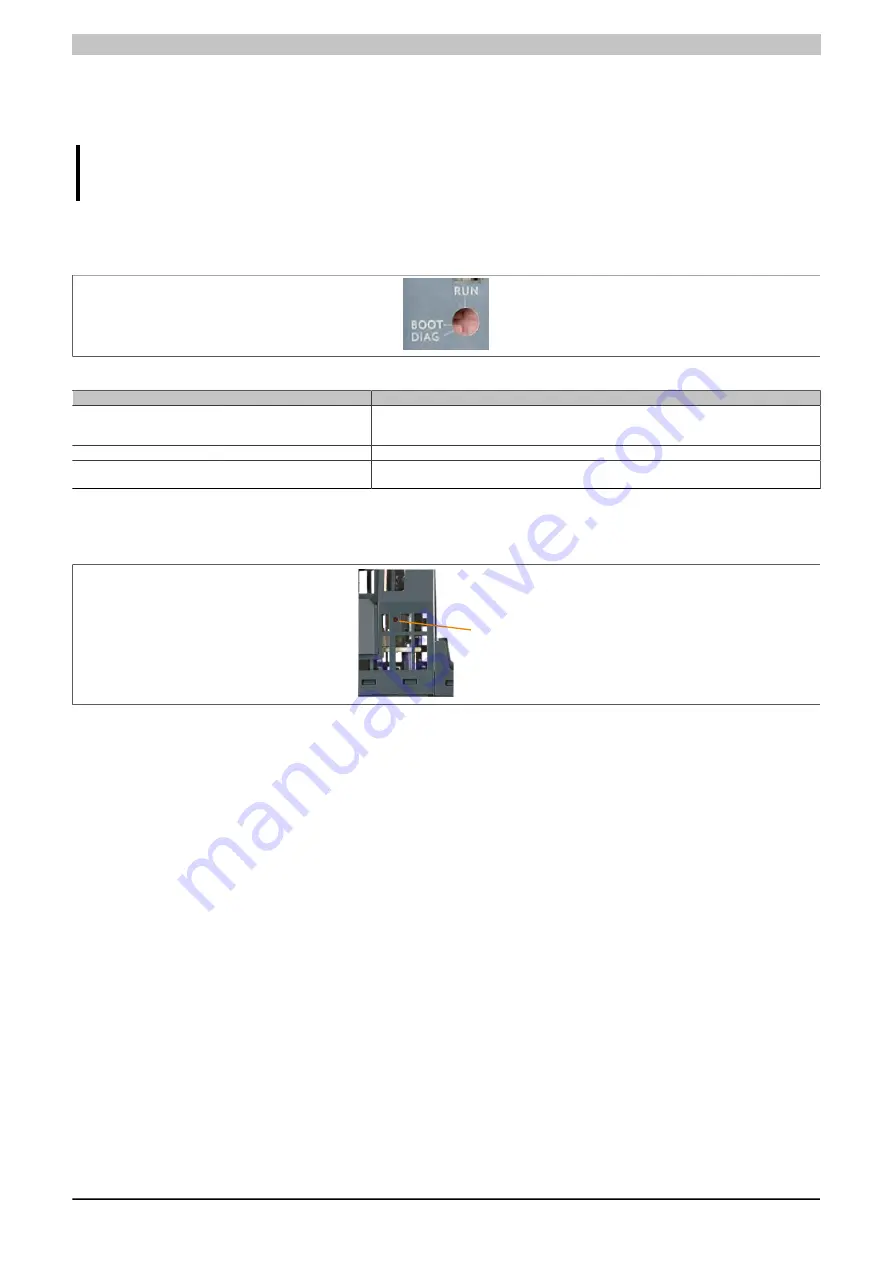
Reset button
Figure 305: X20CPUs - Reset button
The reset button is located below the USB interfaces on the bottom of the housing. It can be pressed with any
small pointed object (e.g. paper clip). Pressing the reset button triggers a hardware reset, which means:
•
All application programs are stopped.
•
All outputs are set to zero.
The PLC then boots into Service mode by default. The boot mode that follows after pressing the reset button can
be defined in Automation Studio.

