X20 system modules • Analog output modules • X20AO4632
X20 system User's Manual 3.10
487
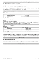
4.4.8.9.4.2 Value for delayed output
Name:
AnalogOutputDelayed00 to AnalogOutputDelayed03
These registers contain the values with which the analog outputs are overwritten after the delay configured with
OutputDelayConfig0x has expired.
Data type
Value
Output Signal
-32768 to 32767
Voltage signal -10 VDC to 10 VDC
INT
0 to 32767
Current signal 0 mA to 20 mA
4.4.8.9.4.3 Configuration of the output delay
Name:
OutputDelayConfig00 to OutputDelayConfig01
Two configurations independent from each other can be created using these registers.
The delay time after which AnalogOutputDelay0x should overwrite the channel can be configured using bits 0 to
13. Using bits 14 and 15, the channel is determined for which the configuration is valid.
Each channel can only be overwritten once. No additional channel can be overwritten while the respective time
is running.
Data type
Value
UINT
See bit structure.
Bit structure:
Bit
Description
Value
Information
0 - 13
Delay time for the selected channel
x
Time in μs
00
Analog output 01
01
Analog output 02
10
Analog output 03
14 - 15
Channel
11
Analog output 04
4.4.8.9.4.4 Delay time for the output value
Name:
AnalogOutputLatchTime00 to AnalogOutputLatchTime01
These registers can be used to read when the respective overwrite value was actually written on the output.
Data type
Value
UINT
Actual delay time
4.4.8.9.4.5 Error register for counter
Name:
Error
There are some limitations because two timers are used. This register is available to the user for reporting these
potential errors.
The error bits are deleted as soon as a valid state is reset.
Data type
Value
UINT
See bit structure.
Bit structure:
Bit
Description
Value
Information
0
OK
0
Analog output 01
1
Has already been overwritten
...
...
0
OK
3
Analog output 04
1
Has already been overwritten
0
OK
4
Timer 01
1
Already in use
0
OK
5
Timer 02
1
Already in use
0
OK
6
Timer 01 and 02
1
Both timers refer to the same channel number
7 - 15
Reserved

