X20 system modules • Digital output modules • X20DO4613
X20 system User's Manual 3.10
1163
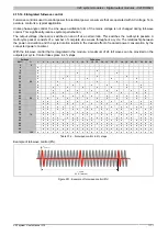
4.15.13.10.7.2 Setting the switch-off time
Name:
ConfigOutput01 to ConfigOutput04
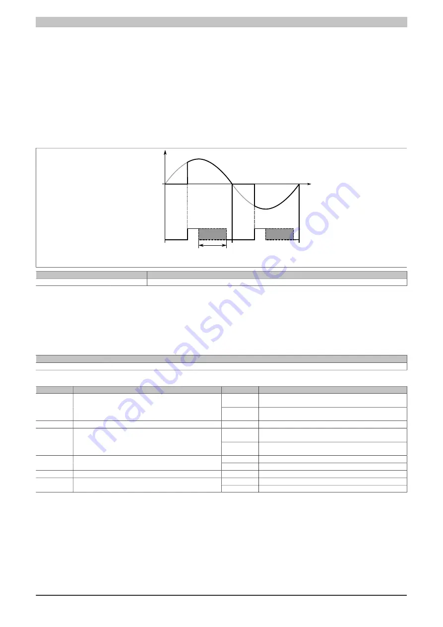
This register defines how far in front of the zero cross-over the internal control signal for the TRIAC is switched off.
Increasing this value may be necessary in order to prevent unwanted firing of the TRIAC in the event of a slight
disturbance in the mains frequency.
With smaller loads, it is important to ensure that this switch off value is not set to large (too early) to prevent
switching off prematurely.
The triac can of course only be fired before the set switch-off time.
"SwitchOffValue" in the AS I/O configuration.
Switch-off value
5 to 50%
1 / f
Triac
Control signal
Data type
Value
Description
USINT
5 to 50
Switch-off time in %
4.15.13.10.7.3 Configuration of the output channels
Name:
ConfigOutput05
The configuration of the output channels are stored in this register.
"Output type digital/analog" and "Output type full/half wave" in the AS I/O configuration
Data type
Value
USINT
See bit structure.
Bit structure:
Bit
Name
Value
Information
0
Output channel 1 is defined as a digital output. The output sta-
tus is defined using bit 0 in the register DigitalOutput 1 - 4
0
Channel 1: Digital / Analog output
1
Output channel 1 is defined as an analog output. The output
status is defined in the register AnalogOutput01
...
...
0
Output channel 4 is defined as a digital output. The output sta-
tus is defined using bit 1 in the register DigitalOutput 1 - 4
3
Channel 4: Digital / Analog output
1
Output channel 2 is defined as an analog output. The output
status is defined in the register AnalogOutput04
0
Full-wave control on output channel 1
4
Channel 1: Full-wave / half-wave control
1)
1
Negative half-wave on output channel 1 is suppressed.
...
...
0
Full-wave control on output channel 4
7
Channel 4: Full-wave / half-wave control
1)
1
Negative half-wave on output channel 4 is suppressed.
1)
Not available in function model 2 - Frequency mode.


