X20 system modules • Digital signal processing modules • X20CM1201
1322
X20 system User's Manual 3.10
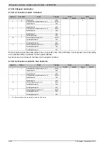
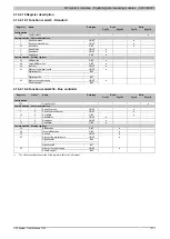
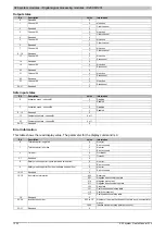
Output states
Bit
Description
Value
Information
0
Reserved
0
0
No action
1
Channel 02
1
Clear channel
2
Reserved
0
0
No action
3
Channel 04
1
Clear channel
4
Reserved
0
0
No action
5
Channel 06
1
Clear channel
6
Reserved
0
0
No action
7
Channel 08
1
Clear channel
8 - 16
Reserved
0
0
No action
17
Channel 02
1
Set channel
18
Reserved
0
0
No action
19
Channel 04
1
Set channel
20
Reserved
0
0
No action
21
Channel 06
1
Set channel
22
Reserved
0
0
No action
23
Channel 08
1
Set channel
24 - 31
Reserved
0
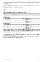
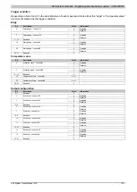
Safe input states
Bit
Description
Value
Information
0
Disabled
0
Activation mask - channel 01
1
Enabled
...
...
0
Disabled
7
Activation mask - channel 08
1
Enabled
8 - 15
Reserved
0
15
Comparative state - channel 01
0 or 1
...
23
Comparative state - channel 08
0 or 1
24 - 31
Reserved
0
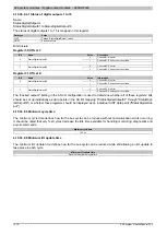
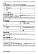
Error information
This table shows the read display value. The parameter for the display command is 0.
Bit
Description
Value
Information
0
No error
0
Tolerance error - negative
1
Error occurred
0
No error
1
Tolerance error - positive
1
Error occurred
0
No timeout
2
Timeout
1
Timeout
3 - 7
Reserved
0
0
No error
8
Safety monitoring error Inputs (hardwire limit switch)
1
Error occurred
0
No error
9
Safety monitoring error Position (software end position)
1
Error occurred
10 - 15
Reserved
0
000
Reserved
001
Negative directional stop state
010
Negative movement
011
Negative directional setup state
100
Stop state
101
Positive directional setup state
110
Positive movement
16 - 18
Error status information
111
Positive directional stop state
19
Reserved
0
000 to 111
Number of the step that does not contain any movement infor-
mation.
20 - 24
Invalid step number
1000
Inactive movement step (tolerance check)
25 - 31
Reserved
0

