X20 system modules • X20 electronics module communication • X20CS1030
X20 system User's Manual 3.10
1577
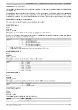
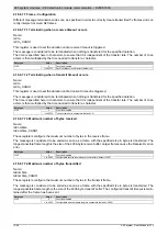
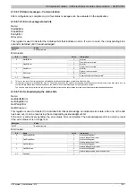
4.18.6.4 LED status indicators
For a description of the various operating modes, see the 2.11.1 "re LEDs" section.
Figure
LED
Color
Status
Description
Off
No power to module
Single flash
RESET mode
Double flash
BOOT mode (during firmware update)
1)
Blinking
PREOPERATIONAL mode
r
Green
On
RUN mode
Off
No power to module or everything OK
Single flash
An I/O error has occurred, see 4.18.6.7.9.1 "Error message status bits"
e
Red
On
Error or reset status
e + r
Red on / Green single flash
Invalid firmware
Tx
Yellow
On
The module transmits data via the RS485/RS422 interface
Rx
Yellow
On
The module receives data via the RS485/RS422 interface
T
Yellow
On
Terminating resistor integrated in the module switched on
1)
Depending on the configuration, a firmware update can take up to several minutes.
4.18.6.5 Pinout
RS485 mode
DATA
GND
Tx
X2
0
C
S
10
30
r
e
Rx
DATA\
GND
T
RS422 mode
TXD
RXD
GND
Tx
X2
0
C
S
10
30
r
e
Rx
TXD\
RXD\
GND
T


