X20 system modules • Digital output modules • X20DO4613
1160
X20 system User's Manual 3.10
4.15.13.10.4 General information
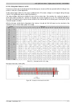
The digital output module was designed for phase control of resistive and inductive loads.
The module is equipped with internal zero-crossing detection. Zero crossing detection is the basis for a software
PLL that generates 200 times the zero crossing frequency. The output signal of the PLL is the base timer for the
2 PWM outputs in both digital and analog mode.
Upon detection of lost periods or periods that are too short, control of the outputs is cut until the PLL is tuned
correctly (can take several seconds). In addition, the "ZeroCrossingStatus" bit is set and the Error LED is enabled
(valid frequency range for the supply is 45 to 65 Hz).
Information:
The jitter of the output signals generated by the PLL and communication can reach 0.5%.
4.15.13.10.5 Digital outputs
The output state of the outputs defined as digital is transferred to the output ports of the control switch in sync with
the connected power mains. The switch-on state is applied when the voltage crosses zero on the positive half-
wave and the switch-off state at the zero crossing for current in each half wave.
4.15.13.10.5.1 Switching state of digital outputs 1 to 4
Name:
DigitalOutput
DigitalOutput01 to DigitalOutput04
The switching state of digital outputs 1 to 4 are stored in this register.
Function model 0 - Standard only:
The "packed outputs" setting in the AS I/O configuration is used to determine whether all of this registers' bits
should be set up individually as data points in the AS I/O mapping ("DigitalOutput01" through "DigitalOutput0x") or
whether this register should be displayed as an individual USINT data point ("DigitalOutput").
Data type
Value
Information
0 to 15
Packed outputs = on
USINT
See bit structure
Packed outputs = off or function model <> 0 - Standard
Bit structure:
Bit
Name
Value
Information
0
Digital output 01 reset
0
DigitalOutput01
1
Digital output 01 set
...
...
0
Digital output 04 reset
3
DigitalOutput04
1
Digital output 04 set
Information:
The states in these registers are only applied when the channels are set to DIGITAL in register
4.15.13.10.7.3 "ConfigOutput05".
When using the setting "packed outputs" ALL channels must be set to DIGITAL. Mixed operation is
not possible.


