X20 system modules • Bus controllers • X20BC0087
544
X20 system User's Manual 3.10
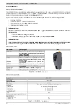
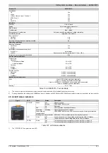
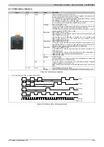
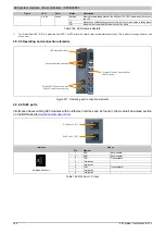
Figure
LED
Color
Status
Description
Blinking
Ethernet activity taking place on the RJ45 port (IF1, IF2) indicated by the respec-
tive LED
On
Indicates an established connection (link), but no communication is taking place
L/A IFx
Green
Off
Indicates that no physical Ethernet connection exists
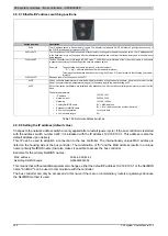
Table 148: LED status indicators
1)
The Status/Error LED "S/E" is a green/red dual LED. The LED blinks red several times immediately after startup. This is a boot message, however, and
not an error.
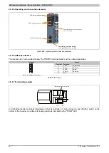
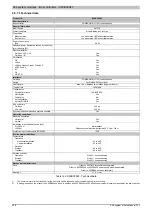
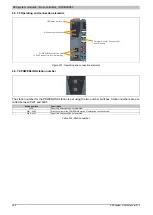
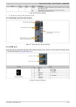
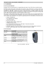
4.5.8.5 Operating and connection elements
LED status indicators
Modbus/TCP connection with
2x RJ45 ports for easy wiring
Network address switches
Terminal block for bus controller
and I/O supply
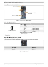
Figure 211: Operating and connection elements
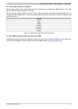
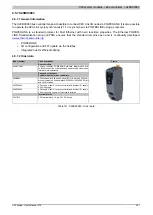
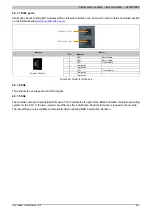
4.5.8.6 RJ45 ports
Information about cabling X20 modules with an Ethernet interface can be found in the module's download section
RJ45 port 1 (IF1)
RJ45 port 2 (IF2)
Pinout
Interface
Pin
Ethernet
1
RXD
Receive data
2
RXD\
Receive data\
3
TXD
Transmit data
4
Termination
5
Termination
6
TXD\
Transmit data\
7
Termination
1
Shielded RJ45 port
8
Termination
Table 149: RJ45 port - Pinout

