X20 system modules • X20 interface module communication • X20IF1030
1774
X20 system User's Manual 3.10
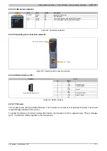
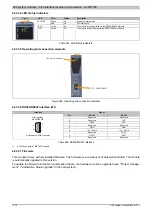
4.23.3.4 LED status indicators
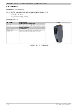
Figure
LED
Color
Status
Description
Green
On
Interface module active
STATUS
Red
On
CPU starting up
RxD
Yellow
On
The module is receiving data via the RS485/RS422 interface
TxD
Yellow
On
The module is sending data via the RS485/RS422 interface
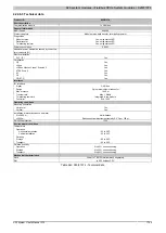
Table 551: LED status indicators
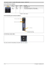
4.23.3.5 Operating and connection elements
LED status indicators
IF1 - RS485/RS422
Figure 580: Operating and connection elements
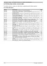
4.23.3.6 RS485/RS422 interface (IF1)
Interface
Pinout
Pin
RS485
RS422
1
Reserved
Reserved
2
Reserved
TxD
1)
3
DATA
RxD
4
Reserved
Reserved
5
GND
GND
6
+5 V / 50 mA
+5 V / 50 mA
7
Reserved
TXD\
1)
8
DATA\
RXD\
User interface
RS485/RS422
1
5
6
9
9-pin female DSUB connector
9
Reserved
Reserved
Table 552: RS485/RS422 interface
1)
RS422 send data is TRISTATE-capable.
4.23.3.7 Firmware
This module comes with preinstalled firmware. The firmware is a component of Automation Studio. The module
is automatically updated to this version.
To update the firmware included in Automation Studio, the hardware must be upgraded (see "Project manage-
ment" / "Automation Studio upgrade" in the help system).


