X20 system modules • Digital input modules • X20DI4375
X20 system User's Manual 3.10
977
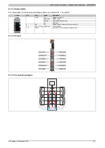
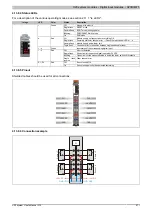
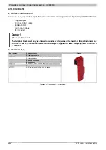
4.13.8.4 Status LEDs
For a description of the various operating modes, see section 2.11.1 "re LEDs".
Image
LED
Color
Status
Description
Off
No power to module
Single flash
RESET mode
Double flash
BOOT mode (during update)
Blinking
PREOPERATIONAL mode
r
Green
On
RUN mode
Off
Module supply not connected or everything OK
Single flash
Summary status for channel error → Check the red channel LEDs 1 - 4
Double flash
Module supply below lower limit
e
Red
Triple flash
Converter error (or transition between single and double flash)
1 - 4
Green
Input status of the corresponding digital input
Off
No error detected
Single flash
Short circuit of respective digital input with +24 VDC
Blinking
Open circuit or the measured value is below the lower switch off threshold
1 - 4
Red
Single flash,
inverse
Other channel error
Off
Sensor supply OK
S1 - S4
Red
On
Sensor supply monitor has detected something
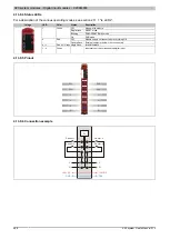
4.13.8.5 Pinout
Shielded cables should be used for all connections.
DI 1
+24 VDC
GND
DI 2
+24 VDC
GND
1
X
20
D
I 4
37
5
2
3 4
DI 3
+24 VDC
GND
DI 4
+24 VDC
GND
r
e
1 2
3 4
S1 S2
S3 S4
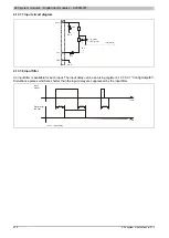
4.13.8.6 Connection example
GND
+24 VDC
GND
+24 VDC
DI
Se
ns
or
1
Se
ns
or
2
Se
ns
or
3
Se
ns
or
4

