X20 system modules • Digital output modules • X20DO4633
1178
X20 system User's Manual 3.10
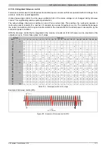
4.15.15.6 Connection example
GND
+24 VDC
GND
+24 VDC
DO
L
N
L
N
Act
ua
to
r
Act
ua
to
r
T 10 A
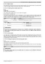
4.15.15.7 OSP hardware requirements
In order to best use OSP mode, make sure when creating the application that the output module and CPU have
separate power supplies.
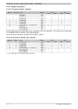
4.15.15.8 Output circuit diagram
DO 4
DO 1
N
L
N
N
VDR
VDR
VDR
Output status 4
Output status 1
Null
I/O status
(LED orange)
I/O status
(LED orange)
External
Power supply
Zero cross
detection
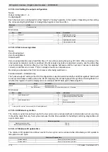
4.15.15.9 External fuses
The following protective circuit must be used for safe operation:
Protective circuit
Value
For the supply lines
Fuse
T 10 A
For the outputs
Fuse
Melting integral I
2
t ≤ 36 A
2
s when tp = 10 ms
With an inductive load
Varistor
1)
e.g. varistor with 275 V
RMS
at 240 VAC
For the supply voltage
Line filter
2)
Attenuation ≥40 dB at 150 kHz, effective range up to 5 MHz
1)
See also section 4.15.15.13 "Operation with inductive loads" on page 1180
2)
Meeting the limit values specified in the standards EN 61131, EN 55011 and EN 55022 (each Class A) requires installation of a line filter in the 240 V supply
line. Line filters such as the Schaffner FN
2412‐8‐
44 can be used.
If periodic ground transients occur on the supply lines (as can occur with upstream inverters), it is necessary to use an asymmetric filter that keeps these
types of changes in potential below a few volts (e.g. "Sinus Plus" from Schaffner) in addition to the symmetric filter.


