X20 system modules • X20 interface module communication • X20IF1082
X20 system User's Manual 3.10
1817
4.23.14.6.1 POWERLINK V1
Switch position
Description
0x00
Operation as managing node.
0x01 - 0xFD
Node number of POWERLINK station. Operation as controlled node.
0xFE - 0xFF
Reserved, switch position not permitted.
Table 595: POWERLINK V1 - Node numbers
4.23.14.6.2 POWERLINK V2
Switch position
Description
0x00
Reserved, switch position not permitted.
0x01 - 0xEF
Node number of POWERLINK station. Operation as controlled node.
0xF0
Operation as managing node.
0xF1 - 0xFF
Reserved, switch position not permitted.
Table 596: POWERLINK V2 - Node numbers
4.23.14.6.3 Ethernet mode
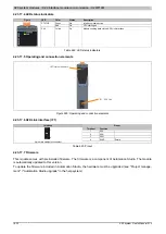
In this mode, the interface is operated as an Ethernet interface. The INA2000 station number can be set using the
B&R Automation Studio software.
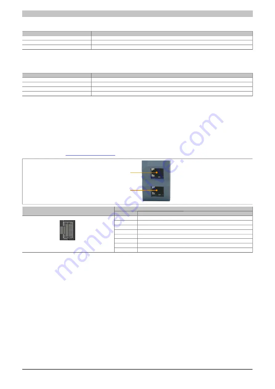
4.23.14.7 RJ45 ports
Information about cabling X20 modules with an Ethernet interface can be found in the module's download section
RJ45 port 2 (X2)
RJ45 port 1 (X1)
Pinout
Interface
Pin
Ethernet
1
RXD
Receive data
2
RXD\
Receive data\
3
TXD
Transmit data
4
Termination
5
Termination
6
TXD\
Transmit data\
7
Termination
1
Shielded RJ45 port
8
Termination
Table 597: RJ45 port - Pinout
4.23.14.8 Firmware
This module comes with preinstalled firmware. The firmware is a component of Automation Studio. The module
is automatically updated to this version.
To update the firmware included in Automation Studio, the hardware must be upgraded (see "Project manage-
ment" / "Automation Studio upgrade" in the help system).


