


594
Appendix A
Manual Changes
Manual Changes
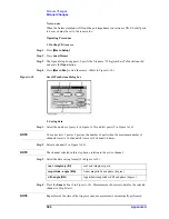
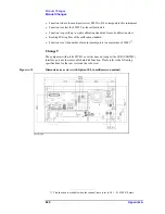
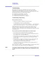
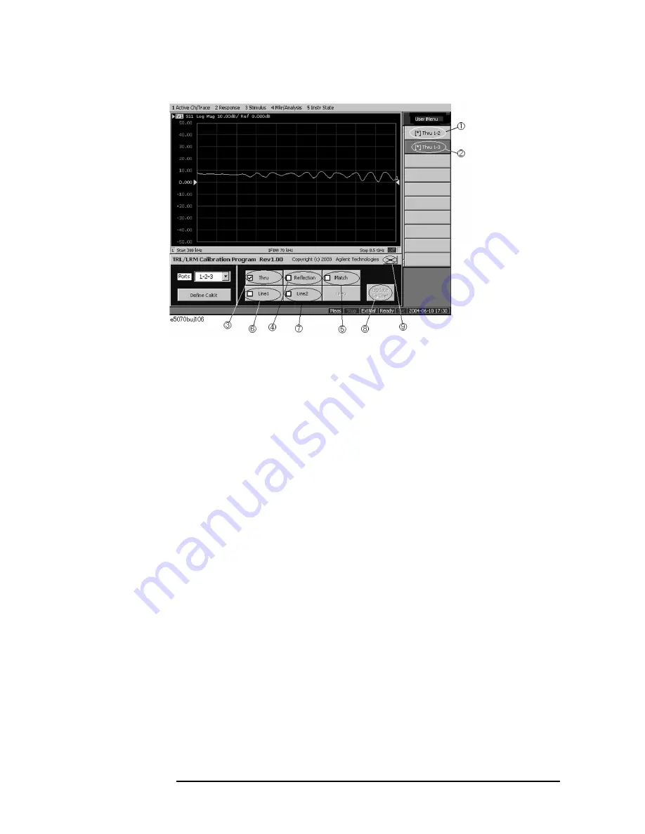
Figure A-9
Example of performing multiport TRL/LRM calibration
Step 5.
Press the
Reflection
button (4 in Figure A-9).
Step 6.
Connect the Reflection standard to test port 1 and press the
[ ]Reflection1
button. The
reflection measurement is performed, and an asterisk appears at the
[ ]Reflection1
button.
Step 7.
Connect the Reflection standard to test port 2 and press the
[ ]Reflection2
button. The
reflection measurement is performed, and an asterisk appears at the
[ ]Reflection2
button.
Step 8.
Connect the Reflection standard to test port 3 and press the
[ ]Reflection3
button. The
reflection measurement is performed, and an asterisk appears at the
[ ]Reflection3
button
and then a check mark [v] also appears on the
Reflection
button.
Step 9.
Press the
Match
button (5 in Figure A-9).
Step 10.
Connect the Match standard to test port 1 and press the
[ ]Match1
button. The match
measurement is performed, and an asterisk appears at the
[ ]Match1
button.
Step 11.
Connect the Match standard to test port 2 and press the
[ ]Match2
button. The match
measurement is performed, and an asterisk appears at the
[ ]Match2
button.
Step 12.
Connect the Match standard to test port 3 and press the
[ ]Match3
button. The match
measurement is performed, and an asterisk appears at the
[ ]Match3
button and then a
check mark [v] also appears on the
Match
button.
Step 13.
Press the
Line1
button (6 in Figure A-9).
Step 14.
Connect the Line 1 standard between test ports 1 and 2 and press the
[ ]Line1 1-2
button.
The line measurement is performed, and an asterisk appears at the
[ ]Line1 1-2
button.
Step 15.
Connect the Line 1 standard between test ports 1 and 3 and press the
[ ]Line1 1-3
button.
The line measurement is performed, and an asterisk appears at the
[ ]Line1 1-3
button and
then a check mark [v] also appears on the
Line1
button.
Step 16.
Press the
Line2
button (7 in Figure A-9).
Step 17.
Connect the Line 2 standard between test ports 1 and 2, and press the
[ ]Line2 1-2
button.
Содержание E5070B
Страница 6: ......
Страница 30: ...24 Contents ...
Страница 34: ...28 Chapter1 Precautions Before contacting us ...
Страница 286: ...280 Chapter6 Data Analysis Using the Equation Editor ...
Страница 430: ...424 Chapter12 Optimizing Measurements Performing a Segment by Segment Sweep segment sweep ...
Страница 479: ...473 14 Controlling E5091A 14 Controlling E5091A This chapter explains how to control the E5091A multiport test set ...
Страница 538: ...532 Chapter15 Measurement Examples Executing Power Calibration ...
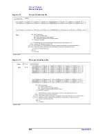
Страница 604: ...598 AppendixA Manual Changes Manual Changes Figure A 12 Two port Touchstone file Figure A 13 Three port Touchstone file ...
Страница 634: ...628 AppendixB Troubleshooting Warning Message ...
Страница 732: ...726 AppendixD Softkey Functions Trigger Menu ...
Страница 740: ...734 AppendixE General Principles of Operation Data Processing ...
Страница 760: ...754 AppendixF Replacing the 8753ES with the E5070B E5071B Comparing Functions ...


