


Appendix A
589
Manual Changes
Manual Changes
A. Manual
Changes
NOTE
When you define each calibration standard, the following points should be considered.
•
Reference impedance Z0 must be set to the same value as the ENA’s system impedance
Z0 value.
•
When you use Line 1, Line 2, and Line 3, their defined frequency ranges must overlap
by at least 10 kHz.
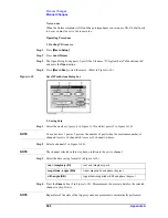
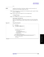
Saving and loading calibration kit definitions
Press the
Save
button (11 in Figure A-4) to save the definition of the current calibration kit
to a file. Press the
Recall
button (12 in Figure A-4) to recall the definition of a calibration
kit from a previously saved file.
NOTE
If you save as “D:\Agilent\Data\TRL_LRM_cal\Default.dat,” the file is handled as the
default definition file. The default definition file is automatically recalled when the macro
starts.
NOTE
The factory-shipped default definition file has the same content as
“D:\Agilent\Trldata\SysDefault.dat.” Copy “D:\Agilent\Trldata\SysDefault.dat” to the
default definition file in order to restore the default definition file to its factory-shipped
condition.
Do not change “D:\Agilent\Trldata\SysDefault.dat.”
Initializing calibration kit definition
Press the
default
button (13 in Figure A-4) to recall the definition of a calibration kit from
the default definition file (“D:
\
Agilent
\
Data\TRL_LRM_cal\Default.dat”).
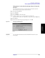
Step 3.
Press the
Close
button (14 in Figure A-4) to finish defining the calibration kit.
3. Performing Calibration
Measure necessary calibration data and enable error correction.
NOTE
The definition of the frequency range of the line standard and match standard used for
measurement must cover the sweep range of the channel for which you perform
calibration.
If the
Thru
,
Reflection
,
Match
, and
Line
keys do not appear, go back to the calibration kit
definition menu and confirm that the frequency range definitions of match and lines are
correctly entered to cover the ENA’s measurement frequency range.
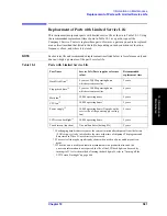
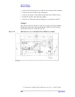
Step 1.
Measure calibration data.
In this example, 2-port TRL/LRM calibration between test ports 1 and 2 (1 in Figure A-5)
is performed by using the Match, Line 1, and Line 2 standards.
Содержание E5070B
Страница 6: ......
Страница 30: ...24 Contents ...
Страница 34: ...28 Chapter1 Precautions Before contacting us ...
Страница 286: ...280 Chapter6 Data Analysis Using the Equation Editor ...
Страница 430: ...424 Chapter12 Optimizing Measurements Performing a Segment by Segment Sweep segment sweep ...
Страница 479: ...473 14 Controlling E5091A 14 Controlling E5091A This chapter explains how to control the E5091A multiport test set ...
Страница 538: ...532 Chapter15 Measurement Examples Executing Power Calibration ...
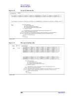
Страница 604: ...598 AppendixA Manual Changes Manual Changes Figure A 12 Two port Touchstone file Figure A 13 Three port Touchstone file ...
Страница 634: ...628 AppendixB Troubleshooting Warning Message ...
Страница 732: ...726 AppendixD Softkey Functions Trigger Menu ...
Страница 740: ...734 AppendixE General Principles of Operation Data Processing ...
Страница 760: ...754 AppendixF Replacing the 8753ES with the E5070B E5071B Comparing Functions ...


