


158
Chapter 4
Calibration
Calibration between Ports of Different Connector Types
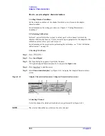
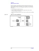
adapter (3 in Figure 4-38).
FWD
Port 1 of the adapter (port 1 of the 2-port Touchstone file) is connected to the test port of
the smaller port number of the E5070B/E5071B.
RVS
Port 2 of the adapter (port 2 of the 2-port Touchstone file) is connected to the test port of
the smaller port number of the E5070B/E5071B.
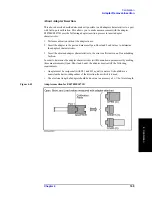
For example, when setting ports 2 to 4, if you want to connect port 1 of the adapter to test
port 4 of the E5070B/E5071B and port 2 of the adapter to test port 2 of the
E5070B/E5071B, select RVS as the port connection mode.
When you select Adapter File, the comment contained in the adapter file is displayed at 4
in Figure 4-38.
NOTE
If the system Z0 written in the adapter file is different from the system Z0 of the
E5070B/E5071B, “file error” is displayed at 4 in Figure 4-38. In this case, you cannot set
the E5070B/E5071B to the adapter calibration mode.
Saving and loading calibration kit settings
You can save the selection of the calibration kit and standard for each test port (the setting
in the Reflection tab) and that for each pair of test ports (the setting in the Thru tab), as well
as load them for restoring whenever needed.
Press the
Save
button (5 in Figure 4-37 or 6 in Figure 4-38) to save the setting to a file.
Press the
Recall
button (4 in Figure 4-37 or 5 in Figure 4-38) or the
Recall Cal Kit
button
(3 in Figure 4-36) to recall the setting from the file.
NOTE
If the calibration kit definition is changed after saving the file, resulting in a contradiction
between the information in the file and that in the calibration kit definition, you can no
longer recall the settings from the file.
Step 5.
Press
Close
(6 in Figure 4-37 or 7 in Figure 4-38) to finish the setting of the calibration
kits.
5. Performing Calibration
Set the E5070B/E5071B to the special calibration mode in which you can use a different
calibration kit for each test port (adapter calibration mode), then perform the calibration.
Step 1.
Press
Set Adapter Calibration Mode
(4 in Figure 4-36) to set the E5070B/E5071B to the
adapter calibration mode.
NOTE
Do not terminate the VBA macro by force.
In the adapter calibration mode, if you terminate the VBA macro forcefully, for example,
with the
key before returning to the normal calibration mode with the
Exit
button, normal calibration can no longer be performed and the label of calibration kit 10
remains altered. To return to the normal calibration mode, restart the firmware of the
E5070B/E5071B. In this case, you cannot restore the label of calibration kit 10.
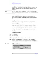
Step 2.
The screen showing the selected calibration kits for each test port and each pair of test ports
Содержание E5070B
Страница 6: ......
Страница 30: ...24 Contents ...
Страница 34: ...28 Chapter1 Precautions Before contacting us ...
Страница 286: ...280 Chapter6 Data Analysis Using the Equation Editor ...
Страница 430: ...424 Chapter12 Optimizing Measurements Performing a Segment by Segment Sweep segment sweep ...
Страница 479: ...473 14 Controlling E5091A 14 Controlling E5091A This chapter explains how to control the E5091A multiport test set ...
Страница 538: ...532 Chapter15 Measurement Examples Executing Power Calibration ...
Страница 604: ...598 AppendixA Manual Changes Manual Changes Figure A 12 Two port Touchstone file Figure A 13 Three port Touchstone file ...
Страница 634: ...628 AppendixB Troubleshooting Warning Message ...
Страница 732: ...726 AppendixD Softkey Functions Trigger Menu ...
Страница 740: ...734 AppendixE General Principles of Operation Data Processing ...
Страница 760: ...754 AppendixF Replacing the 8753ES with the E5070B E5071B Comparing Functions ...


