


184
Chapter 4
Calibration
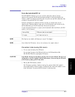
Changing the Calibration Kit Definition
determined through measurement or by dividing the exact physical
length of the standard by the velocity coefficient.
Loss
This is used to determine the energy loss caused by the skin effect
along the length (one-way) of the coaxial cable. Loss is defined using
the unit of
Ω
/s at 1 GHz. In many applications, using the value 0 for
the loss should not result in significant error. The loss of a standard is
determined by measuring the delay (sec.) and the loss at 1 GHz and
then substituting them in the formula below.
Loss
Ω
s
----
⎝ ⎠
⎛ ⎞
loss dB
(
)
Z
0
Ω
( )
×
4.3429
dB
(
)
delay s
( )
×
---------------------------------------------------------
=
C0, C1, C2, C3
It is extremely rare for an OPEN standard to have perfect reflection
characteristics at high frequencies. This is because the fringe
capacitance of the standard causes a phase shift that varies along with
the frequency. For internal calculation of the analyzer, an OPEN
capacitance model is used. This model is described as a function of
frequency, which is a polynomial of the third degree. Coefficients in
the polynomial may be defined by the user. The formula for the
capacitance model is shown below.
C
C
0
(
)
C
1
F
×
(
)
C
2
F
2
×
(
)
C
3
F
3
×
(
)
+
+
+
=
F: measurement frequency
C0 unit: (Farads) (constant in the polynomial)
C1 unit: (Farads/Hz)
C2 unit: (Farads/Hz2)
C3 unit: (Farads/Hz3)
L0, L1, L2, L3
It is extremely rare for a SHORT standard to have perfect reflection
characteristics at high frequencies. This is because the residual
inductance of the standard causes a phase shift that varies along with
the frequency. It is not possible to eliminate this effect. For internal
calculation of the analyzer, a short-circuit inductance model is used.
This model is described as a function of frequency, which is a
polynomial of the third degree. Coefficients in the polynomial may be
defined by the user. The formula for the inductance model is shown
below.
L
L
0
(
)
L
1
F
×
(
)
L
2
F
2
×
(
)
L
3
F
3
×
(
)
+
+
+
=
F: Measurement frequency
L0 unit: [Farads] (the constant in the polynomial)
L1 unit: [Farads/Hz]
L2 unit: [Farads/Hz2]
L3 unit: [Farads/Hz3]
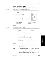
In most existing calibration kits, THRU standards are defined as “zero-length THRU,” i.e.,
the delay and loss are both “0”. Such a THRU standard does not exist, however.
Calibration must be done with two test ports interconnected directly.
NOTE
The measurement accuracy depends on the conformity of the calibration standard to its
definition. If the calibration standard has been damaged or worn out, the accuracy will
decrease.
Содержание E5070B
Страница 6: ......
Страница 30: ...24 Contents ...
Страница 34: ...28 Chapter1 Precautions Before contacting us ...
Страница 286: ...280 Chapter6 Data Analysis Using the Equation Editor ...
Страница 430: ...424 Chapter12 Optimizing Measurements Performing a Segment by Segment Sweep segment sweep ...
Страница 479: ...473 14 Controlling E5091A 14 Controlling E5091A This chapter explains how to control the E5091A multiport test set ...
Страница 538: ...532 Chapter15 Measurement Examples Executing Power Calibration ...
Страница 604: ...598 AppendixA Manual Changes Manual Changes Figure A 12 Two port Touchstone file Figure A 13 Three port Touchstone file ...
Страница 634: ...628 AppendixB Troubleshooting Warning Message ...
Страница 732: ...726 AppendixD Softkey Functions Trigger Menu ...
Страница 740: ...734 AppendixE General Principles of Operation Data Processing ...
Страница 760: ...754 AppendixF Replacing the 8753ES with the E5070B E5071B Comparing Functions ...


