TMPR4937 Revision History
1
TMPR4937 Revision History
Page
Rev 1.1 Manual
Changes and Additions to Rev 1.1
References
64-bit TX System RISC TX49/H3 Core Architecture User’s
Manual
64-bit TX System RISC
TX49/H2, TX49/H3, TX49/H4 Core
Architecture
1-1
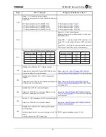
Modified line 5 of the body text in Section 1.1,
Overview
For details of the TX49/H3 core such as instruction sets, see
“64-bit TX System RISC TX49/H3 Core Architecture”.
For details of the TX49/H3 core such as instruction sets,
see “64-bit TX System RISC
TX49/H2, TX49/H3, TX49/H4
Core Architecture”.
3-7
Table 3.1.9 AC-link Interface Signals
Added the following text to the description of the SDIN[1]
signal
When this pin is used as SDIN[1], pull down by the resister
on the board. (Regarding the value of register, please ask
the Engineering Department in Toshiba).
3-7
Table 3.1.9 AC-link Interface Signals
Added the following text to the description of the SDIN[0]
signal
When this pin is used as SDIN[0], pull down by the resister
on the board. (Regarding the value of register, please ask
the Engineering Department in Toshiba).
3-7
Table 3.1.9 AC-link Interface Signals
Added the following text to the description of the BITCLK
signal
When this pin is used as BITCLK, pull down by the resister
on the board. (Regarding the value of register, please ask
the Engineering Department in Toshiba).
3-8
Table 3.1.11 Extended EJTAG Interface Signals
Changed the description of the TRST
*
signal
When an EJTAG probe is not connected, this pin must be
fixed to low. When connecting an EJTAG probe, prevent
floating, for example, by connecting a pull-up resistor.
TRST
*
pin must be pulled down (ex.10 k
Ω
).
3-11
Table 3.2.2 Boot Configuration Specified with the
ADDR[19:0] Signals (1/2)
Modified the description of the ADDR[17:15].
Reserved
Reserved
Used for testing. This signal will not be set to 0 upon
booting.
4-1
Modified line 2 of the introduction in Chapter 4,
Address
Mapping
Please refer to "64 bit TX System RISC TX49/H3 Core
Architecture" about the details of mapping to a physical
address from the virtual address of TX49/H3 core.
Please refer to "
64-bit
TX System RISC
TX49/H2, TX49/H3,
TX49/H4
Core Architecture" about the details of mapping to
a physical address from the virtual address of TX49/H3
core.
5-2
Table 5.2.1 Configuration Register Mapping
Deleted the description of the Jump Address Register
Deleted
Summary of Contents for TX49 TMPR4937
Page 1: ...64 Bit TX System RISC TX49 Family TMPR4937 Rev 2 0 ...
Page 4: ......
Page 13: ...Table of Contents ix TMPR4937 Revision History 1 ...
Page 14: ...Table of Contents x ...
Page 15: ...Handling Precautions ...
Page 16: ......
Page 18: ...1 Using Toshiba Semiconductors Safely 1 2 ...
Page 40: ...3 General Safety Precautions and Usage Considerations 3 18 ...
Page 42: ...4 Precautions and Usage Considerations 4 2 ...
Page 43: ...TMPR4937 2005 3 Rev 2 0 ...
Page 44: ......
Page 52: ...Chapter 1 Overview and Features 1 6 ...
Page 156: ...Chapter 7 External Bus Controller 7 56 ...
Page 491: ...Chapter 16 Removed 16 1 16 Removed ...
Page 492: ...Chapter 16 Removed 16 2 ...
Page 493: ...Chapter 17 Removed 17 1 17 Removed ...
Page 494: ...Chapter 17 Removed 17 2 ...
Page 495: ...Chapter 18 Removed 18 1 18 Removed ...
Page 496: ...Chapter 18 Removed 18 2 ...
Page 497: ...Chapter 19 Removed 19 1 19 Removed ...
Page 498: ...Chapter 19 Removed 19 2 ...
Page 506: ...Chapter 20 Extended EJTAG Interface 20 8 ...
Page 530: ...Chapter 22 Pinout and Package Information 22 10 ...
Page 542: ...Chapter 24 Parts Number when Ordering 24 2 ...

