Chapter 10 PCI Controller
10-23
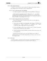
10.3.14 Set Configuration Space
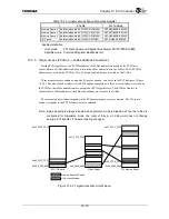
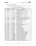
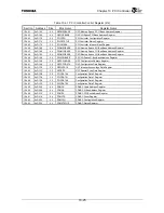
In Table 10.5.1, the values for the registers inside the PCI Configuration Space Register that have a
gray background can be rewritten using one of the two following methods.
10.3.14.1 Set the Configuration Space Using EEPROM
Load values during Reset by connecting standard 93C46/93C48 EEPROM to a dedicated port.
The PCI Controller reads 16-bit half-word data for address 2n (n: 0, 1, 2, …, 31) of the PCI
Configuration Space from EEPROM address (2n + 2 - 4(n mod 2)). Also, 16-bit data is read in
order from the upper bits to the lower bits. The EEPROM values that correspond to the registers in
Table 10.5.1 that have a white background are “don’t care”.
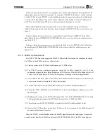
10.3.14.2 Set the Configuration Space Using Software Reset
By using the following procedure, it is possible to use the software to set the configuration
space without using EEPROM.
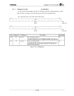
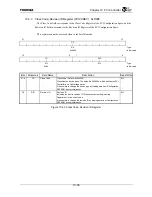
(1) Set the value to be loaded in the Configuration Data 0 Register (PCICDATA0), the
Configuration Data 1 Register (PCICDATA1), the Configuration Data 2 Register
(PCICDATA2), and the Configuration Data 3 Register (PCICDATA3).
(2) Set the Load Configuration Data Register bit (LCFG) of the PCI Controller Configuration
Register (PCICCFG) and the Software Reset bit (SRST).
(3) Clear the Software Reset bit (PCICCFG.SRST) at least four PCI Bus clock cycles later. This
starts loading the data.
After these processes are complete, please set the Target Configuration Access Ready bit
(PCICCFG.TCAR) of the PCI Controller Configuration Register to be able to accept access to the
PCI Configuration space.
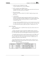
10.3.15 PCI Clock
The PCI bus signals are synchronized by the PCI clock applied to the PCICLKIN pin. Therefore, in
PCI clock output mode, the PCI output clock must be connected to the PCICLKIN pin.
Summary of Contents for TX49 TMPR4937
Page 1: ...64 Bit TX System RISC TX49 Family TMPR4937 Rev 2 0 ...
Page 4: ......
Page 13: ...Table of Contents ix TMPR4937 Revision History 1 ...
Page 14: ...Table of Contents x ...
Page 15: ...Handling Precautions ...
Page 16: ......
Page 18: ...1 Using Toshiba Semiconductors Safely 1 2 ...
Page 40: ...3 General Safety Precautions and Usage Considerations 3 18 ...
Page 42: ...4 Precautions and Usage Considerations 4 2 ...
Page 43: ...TMPR4937 2005 3 Rev 2 0 ...
Page 44: ......
Page 52: ...Chapter 1 Overview and Features 1 6 ...
Page 156: ...Chapter 7 External Bus Controller 7 56 ...
Page 491: ...Chapter 16 Removed 16 1 16 Removed ...
Page 492: ...Chapter 16 Removed 16 2 ...
Page 493: ...Chapter 17 Removed 17 1 17 Removed ...
Page 494: ...Chapter 17 Removed 17 2 ...
Page 495: ...Chapter 18 Removed 18 1 18 Removed ...
Page 496: ...Chapter 18 Removed 18 2 ...
Page 497: ...Chapter 19 Removed 19 1 19 Removed ...
Page 498: ...Chapter 19 Removed 19 2 ...
Page 506: ...Chapter 20 Extended EJTAG Interface 20 8 ...
Page 530: ...Chapter 22 Pinout and Package Information 22 10 ...
Page 542: ...Chapter 24 Parts Number when Ordering 24 2 ...


