Chapter 3 Signals
3-10
3.2 Boot
Configuration
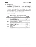
The ADDR[19:0] and DATA[15:0] signals can also function as configuration signals for initially setting
various functions upon booting the system. The states of the configuration signals immediately after the
RESET* or CGRESET* signal is deasserted are read as initial values for the TX4937 internal registers. A
High signal level sets a value of 1 and a Low signal level sets a value of 0.
All configuration signals are provided with internal pull-up resistors. To drive a signal Low, pull down the
corresponding pin on the board using an approx. 4.7 k
Ω
resistor. Driving a signal High does not require a
pull-down resistor. Any signals defined as Reserved should not be pulled down.
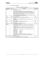
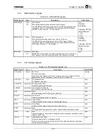
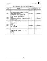
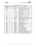
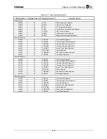
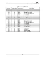
Table 3.2.1 lists the functions that can be set using configuration signals. Table 3.2.2 and Table 3.2.3
describe each configuration signal.
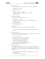
Table 3.2.1 Functions that Can be Set Using Configuration Signals
Peripheral
Function
Functions that Can be Set
Configuration
Signal
PCI controller operating mode (satellite or host) ADDR[19]
Division ratio of PCICLK[5:0] to CPUCLK
ADDR[11:10]
PCI controller
PCI bus arbiter selection (internal or external)
DATA[2]
Division ratio of SYSCLK to GBUSCLK
ADDR[14:13]
Boot device selection
Division ratio of the external bus controller clock upon booting
ADDR[8:6]
BE[3:0]
*
/BWE[3:0]
*
function selection upon booting
DATA[5]
Handling of the ACK signal upon booting (internal or external)
DATA[4]
External bus
controller
Data bus width for the boot device
DATA[1:0]
Clock
Division ratio of CPUCLK to MASTERCLK
ADDR[3:0]
Shared pin function setting
ADDR[18], ADDR[9]
DATA[6], DATA[3]
Endian setting
ADDR[12]
Board information setting
DATA[15:8]
Others
Controlling built-in timer interrupts of the TX49/H3 core
DATA[7]
Summary of Contents for TX49 TMPR4937
Page 1: ...64 Bit TX System RISC TX49 Family TMPR4937 Rev 2 0 ...
Page 4: ......
Page 13: ...Table of Contents ix TMPR4937 Revision History 1 ...
Page 14: ...Table of Contents x ...
Page 15: ...Handling Precautions ...
Page 16: ......
Page 18: ...1 Using Toshiba Semiconductors Safely 1 2 ...
Page 40: ...3 General Safety Precautions and Usage Considerations 3 18 ...
Page 42: ...4 Precautions and Usage Considerations 4 2 ...
Page 43: ...TMPR4937 2005 3 Rev 2 0 ...
Page 44: ......
Page 52: ...Chapter 1 Overview and Features 1 6 ...
Page 156: ...Chapter 7 External Bus Controller 7 56 ...
Page 491: ...Chapter 16 Removed 16 1 16 Removed ...
Page 492: ...Chapter 16 Removed 16 2 ...
Page 493: ...Chapter 17 Removed 17 1 17 Removed ...
Page 494: ...Chapter 17 Removed 17 2 ...
Page 495: ...Chapter 18 Removed 18 1 18 Removed ...
Page 496: ...Chapter 18 Removed 18 2 ...
Page 497: ...Chapter 19 Removed 19 1 19 Removed ...
Page 498: ...Chapter 19 Removed 19 2 ...
Page 506: ...Chapter 20 Extended EJTAG Interface 20 8 ...
Page 530: ...Chapter 22 Pinout and Package Information 22 10 ...
Page 542: ...Chapter 24 Parts Number when Ordering 24 2 ...

