Chapter 21 Electrical Characteristics
21-5
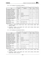
21.5 AC characteristics
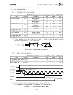
21.5.1 MASTERCLK
AC
characteristics
(Tc = 0 – 70
°
C, V
CCIO
= 3.3 V
±
0.2 V, V
CCInt
= 1.5 V
±
0.1 V, VSS = 0 V)
Item Symbol Conditions
Min.
Max.
Unit
Boot configuration
ADDR[2]=H
7.5 80 ns
MASTERCLK Cycle
t
MCP
Boot configuration
ADDR[2]=L
30 320 ns
Boot configuration
ADDR[2]=H
12.5 133.3 MHz
MASTERCLK Frequency
*
1)
f
MCK
Boot Configuration
ADDR[2]=L
3.125 33.3 MHz
MASTERCLK High Time
t
MCH
2
⎯
ns
MASTERCLK Low Time
t
MCL
2
⎯
ns
TMPR4937XBG-300 50
300
CPUCLK Frequency
f
CPU
TMPR4937XBG-333 50
333
MHz
MASTERCLK Rise Time
t
MCR
⎯
1.5 ns
MASTERCLK Fall Time
t
MCF
⎯
1.5 ns
*
1) TX4937 operation is only guaranteed when the power is stable, PLL secures the PLL oscillation
stability time tMCP_PLL and is in the Enable state.
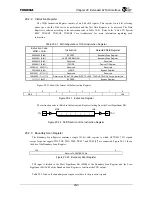
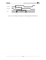
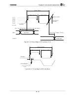
Figure 21.5.1 Timing Diagram: MASTERCLK
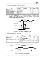
21.5.2 Power
on
AC
characteristics
(Tc = 0 – 70
°
C, V
CCIO
= 3.3 V
±
0.2 V, V
CCInt
= 1.5 V
±
0.1 V, VSS = 0 V)
Item Symbol Conditions
Min.
Max.
Unit
PLL Oscillation Stability Time
t
MCP_PLL
10
ms
CGRESET
*
Width Time
f
MCK_PLL
1
ms
RESET
*
Width Time
t
MCH_PLL
1
⎯
ms
*
1) V
CCInt
and V
CCIO
must start up sumultaneously, or V
CCInt
must be first.
The difference of the stand up time ota power supply within 100 m seconds.
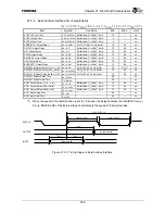
Figure 21.5.2 Timing Diagram: Power On Reset
t
MCH
t
MCL
t
MCP
MASTERCLK
0.8 V
CC
0.2 V
CC
t
MCR
t
MCF
t
MCP_PLL
t
MCK_PLL
MASTERCLK Oscillation Stability Time
t
MCH_PLL
V
CCInt
, V
CCIO
*
1)
PLL_Vdd1_A,
PLL_Vdd2_A
MASTERCLK
CGRESET
*
RESET
*
Summary of Contents for TX49 TMPR4937
Page 1: ...64 Bit TX System RISC TX49 Family TMPR4937 Rev 2 0 ...
Page 4: ......
Page 13: ...Table of Contents ix TMPR4937 Revision History 1 ...
Page 14: ...Table of Contents x ...
Page 15: ...Handling Precautions ...
Page 16: ......
Page 18: ...1 Using Toshiba Semiconductors Safely 1 2 ...
Page 40: ...3 General Safety Precautions and Usage Considerations 3 18 ...
Page 42: ...4 Precautions and Usage Considerations 4 2 ...
Page 43: ...TMPR4937 2005 3 Rev 2 0 ...
Page 44: ......
Page 52: ...Chapter 1 Overview and Features 1 6 ...
Page 156: ...Chapter 7 External Bus Controller 7 56 ...
Page 491: ...Chapter 16 Removed 16 1 16 Removed ...
Page 492: ...Chapter 16 Removed 16 2 ...
Page 493: ...Chapter 17 Removed 17 1 17 Removed ...
Page 494: ...Chapter 17 Removed 17 2 ...
Page 495: ...Chapter 18 Removed 18 1 18 Removed ...
Page 496: ...Chapter 18 Removed 18 2 ...
Page 497: ...Chapter 19 Removed 19 1 19 Removed ...
Page 498: ...Chapter 19 Removed 19 2 ...
Page 506: ...Chapter 20 Extended EJTAG Interface 20 8 ...
Page 530: ...Chapter 22 Pinout and Package Information 22 10 ...
Page 542: ...Chapter 24 Parts Number when Ordering 24 2 ...


