Chapter 21 Electrical Characteristics
21-2
21.3 DC characteristics
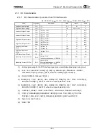
21.3.1 DC characteristics of pins other than PCI Interface pins
(Tc
= 0 - 70
°
C, V
ddIO
= 3.3V
±
0.2V, V
CCInt
= 1.5V
±
0.1V, V
SS
= 0V)
Item Symbol Condition
Min.
Max.
Unit
Low-level Input Voltage
V
IL1
(1)
−
0.3 0.8 V
High-level Input Voltage
V
IH1
(1) 2.0
V
CCIO
+ 0.3
V
Low-level Output Current
I
OL1
I
OL2
(2)V
OL
= 0.4 V
(3)V
OL
= 0.4 V
8
4
⎯
⎯
mA
mA
Low-level Output Current
I
OL3
I
OL4
(4)V
OL
= 0.4 V
(5)V
OL
= 0.4 V
16
8
⎯
⎯
mA
mA
High-level Output Current
I
OH1
I
OH2
(2)V
OH
= 2.4 V
(3)V
OH
= 2.4 V
⎯
⎯
−
8
−
4
mA
mA
High-level Output Current
I
OH3
I
OH4
(4)V
OH
= 2.4 V
(5)V
OH
= 2.4 V
⎯
⎯
−
16
−
8
mA
mA
Low-level Input Leak
Current
I
IL1
I
IL2
(6)V
IN
=V
SS
(7)V
IN
=V
SS
−
10
−
200
10
−
10
µ
A
µ
A
High-level Input Leak
Current
I
IH1
(8)V
IN
=V
CCIO
−
10 10
µ
A
Hi-Z Output Leak Current
I
OZ
(9)
−
10 10
µ
A
Operating Current (Internal)
I
CCInt
V
ddIN
= 1.6 V,
Internal core frequency = 300 MHz
⎯
500 mA
Operating Current (I/O Pin)
I
CCIO
V
ddIO
= 3.5 V,
External bus frequency = 100 MHz
Pin capacitance load = 25 pF
⎯
400 mA
(1) : All input pins except for the PCI interface signal pins, and all bidirectional pins (during input)
(2) : ACE
*
, ACK
*
, BUSSPRT
*
, BWE[3:0]
*
, CE[7:0]
*
, DMAACK[3:0], DMADONE
*
, WDRST
*
,
HALTDOZE, PIO[7:0], RTS[1:0], SWE
*,
SYSCLK, TIMER[1:0] and TXD[1:0]
(3) : DCLK, PCST[8:0], TDO and TPC[3:1]
(4) :
ADDR[19:0], CAS
*
, CB[7:0], CKE, DATA[63:0], DQM[7:0], OE
*
, RAS
*
, SDCLK[3:0],
SDCLKIN, SDCS[3:0]
*
, and WE
*
when drive capacity is set to 16 mA.
(5) :
ADDR[19:0], CAS
*
, CB[7:0], CKE, DATA[63:0], DQM[7:0], OE
*
, RAS
*
, SDCLK[3:0],
SDCLKIN, SDCS[3:0]
*
, and WE
*
when drive capacity is set to 8 mA.
(6) : CGRESET
*
, RESET
*
, TRST
*
, BYPASSPLL
*
, MASTERCLK, SDCLKIN and SDIN[1]
(7) : CTS[1:0]
*
, DMAREQ[3:0], DMADONE
*
, RXD[1:0], SCLK, TCLK, INT[5:0], TCK, TDI,
TEST[4:0]
*
, TMS, ACK
*
, CB[7:0], DATA[63:0], ADDR[19:0], NMI
*
and PIO[7:0]
(8) : Signal in (6) and (7) above
(9) : DCLK, TDO
Summary of Contents for TX49 TMPR4937
Page 1: ...64 Bit TX System RISC TX49 Family TMPR4937 Rev 2 0 ...
Page 4: ......
Page 13: ...Table of Contents ix TMPR4937 Revision History 1 ...
Page 14: ...Table of Contents x ...
Page 15: ...Handling Precautions ...
Page 16: ......
Page 18: ...1 Using Toshiba Semiconductors Safely 1 2 ...
Page 40: ...3 General Safety Precautions and Usage Considerations 3 18 ...
Page 42: ...4 Precautions and Usage Considerations 4 2 ...
Page 43: ...TMPR4937 2005 3 Rev 2 0 ...
Page 44: ......
Page 52: ...Chapter 1 Overview and Features 1 6 ...
Page 156: ...Chapter 7 External Bus Controller 7 56 ...
Page 491: ...Chapter 16 Removed 16 1 16 Removed ...
Page 492: ...Chapter 16 Removed 16 2 ...
Page 493: ...Chapter 17 Removed 17 1 17 Removed ...
Page 494: ...Chapter 17 Removed 17 2 ...
Page 495: ...Chapter 18 Removed 18 1 18 Removed ...
Page 496: ...Chapter 18 Removed 18 2 ...
Page 497: ...Chapter 19 Removed 19 1 19 Removed ...
Page 498: ...Chapter 19 Removed 19 2 ...
Page 506: ...Chapter 20 Extended EJTAG Interface 20 8 ...
Page 530: ...Chapter 22 Pinout and Package Information 22 10 ...
Page 542: ...Chapter 24 Parts Number when Ordering 24 2 ...


