Chapter 10 PCI Controller
10-27
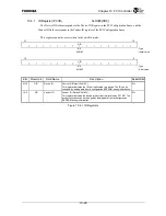
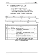
10.4.2 PCI Status, Command Register (PCISTATUS)
0xD004
The upper 16 bits correspond to the Status Register in the PCI Configuration Space, and the lower 16 bits
correspond to the Command Register in the PCI Configuration Space.
This register cannot be accessed when in the Satellite mode. However, it is possible to read some values of
the upper 16 bits from the Satellite Mode PCI Status Register (PCISSTATUS).
31 30 29 28 27 26 25 24 23 22 21 20 19 16
DPE SSE RMA RTA STA
DT
MDPE FBBCP
Reserved
66MCP
CL Reserved
R/W1C
R/W1C
R/W1C
R/W1C R/W1C R R/W1C
R R R
:
Type
0 0 0 0 0
01
0 1 1 1
:
Initial
value
15 10 9 8 7 6 5 4 3 2 1 0
Reserved FBBEN SEREN STPC PEREN VPS
MWIEN SC
BM
MEMSP
IOSP
R/W
R/W R R/W R R/W R R/W
R/W
R/W
:
Type
0 0 0 0 0 0 0 0/1 0 0
:
Initial
value
Bit Mnemonic Field
Name
Description
Read/Write
31 DPE
Detected Parity
Error
Detected Parity Error (Default: 0)
Indicates that a parity error was detected. A parity error is detected in the
three following situtations:
•
Detected a data parity error as the Read command PCI initiator.
•
Detected a data parity error as the Write command PCI target.
•
Detected an address parity error.
This bit is set regardless of the setting of the Parity Error Response bit
(PCISTATUS.PEREN) of the PCI Status, Command Register.
1: Detected a parity error.
0: Did not detect a parity error.
R/W1C
30 SSE
Signaled System
Error
Signaled System Error (Default: 0)
Detects either an address parity error or a special cycle data parity error.
This bit is set when the SERR
*
signal is asserted.
1: Asserted the SERR
*
signal
0: Did not assert the SERR
*
signal.
R/W1C
29 RMA
Received Master
Abort
Received Master Abort (Default: 0)
This bit is set when a Master Abort aborts a PCI Bus Transaction when the
PCI Controller operates as the PCI initiator (except for special cycles).
1: Transaction was aborted by a Master Abort.
0: Transaction was not aborted by a Master Abort.
R/W1C
28 RTA
Received Target
Abort
Received Target Abort (Default: 0)
This bit is set when a Target Abort aborts a PCI Bus Transaction when the
PCI Controller operates as the PCI initiator.
1: Transaction was aborted by a Target Abort.
0: Transaction was not aborted by a Target Abort.
R/W1C
27 STA
Signaled Target
Abort
Signaled Target Abort (Default: 0)
This bit is set when a Target Abort aborts a PCI Bus Transaction when the
PCI Controller operates as the PCI target.
1: Bus transaction was aborted by a Target Abort.
0: Bus transaction was not aborted by a Target Abort.
R/W1C
26:25
DT
DEVSEL Timing
DEVSEL Timing (Fixed Value: 01)
Three DEVSEL assert timings are defined in the PCI 2.2 Specifications:
00b = Fast; 01b = Medium; 10b = Slow; 11b = Reserved).
With the exception of Read Configuration and Write Configuration, when
the PCI Controller is the PCI target, the DEVSEL signal is asserted to a
certain bus command and indicates the slowest speed for responding to
the PCI Bus Master.
R
Figure 10.4.2 PCI Status, Command Register (1/3)
Summary of Contents for TX49 TMPR4937
Page 1: ...64 Bit TX System RISC TX49 Family TMPR4937 Rev 2 0 ...
Page 4: ......
Page 13: ...Table of Contents ix TMPR4937 Revision History 1 ...
Page 14: ...Table of Contents x ...
Page 15: ...Handling Precautions ...
Page 16: ......
Page 18: ...1 Using Toshiba Semiconductors Safely 1 2 ...
Page 40: ...3 General Safety Precautions and Usage Considerations 3 18 ...
Page 42: ...4 Precautions and Usage Considerations 4 2 ...
Page 43: ...TMPR4937 2005 3 Rev 2 0 ...
Page 44: ......
Page 52: ...Chapter 1 Overview and Features 1 6 ...
Page 156: ...Chapter 7 External Bus Controller 7 56 ...
Page 491: ...Chapter 16 Removed 16 1 16 Removed ...
Page 492: ...Chapter 16 Removed 16 2 ...
Page 493: ...Chapter 17 Removed 17 1 17 Removed ...
Page 494: ...Chapter 17 Removed 17 2 ...
Page 495: ...Chapter 18 Removed 18 1 18 Removed ...
Page 496: ...Chapter 18 Removed 18 2 ...
Page 497: ...Chapter 19 Removed 19 1 19 Removed ...
Page 498: ...Chapter 19 Removed 19 2 ...
Page 506: ...Chapter 20 Extended EJTAG Interface 20 8 ...
Page 530: ...Chapter 22 Pinout and Package Information 22 10 ...
Page 542: ...Chapter 24 Parts Number when Ordering 24 2 ...

