Chapter 12 Timer/Counter
12-10
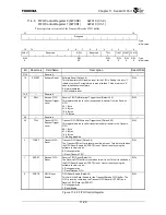
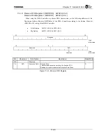
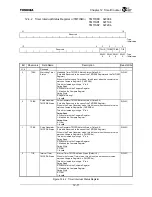
12.4.1 Timer
Control
Register
n
(TMTCRn)
TMTCR0 0xF000
TMTCR1
0xF100
TMTCR2
0xF200
31
16
Reserved
:
Type
:
Initial
value
15 8 7 6 5 4 3 2
1 0
Reserved TCE
CCDE CRE
Reserved
ECES
CCS TMODE
R/W
R/W
R/W
R/W
R/W R/W
:
Type
0 0 0 0 0 00 :
Initial
value
Bit Mnemonic Field
Name
Description
Read/Write
31:8
Reserved
⎯
7 TCE
Timer Counter
Enable
Timer Count Enable (Default: 0)
This field controls whether the counter runs or stops.
When in the Watchdog mode, counter operation only stops when the
Watchdog Timer Disable bit (TMWTMR2.WDIS) of the Watchdog Timer
Mode Register is set. When the Watchdog Timer Disable bit is cleared, the
value of this Timer Count Enable bit becomes “0”, but the count continues.
0: Stop counter (the counter is also cleared to “0” when CRE = 1)
1: Counter operation
R/W
6 CCDE
Counter Clock
Divider Enable
Counter Clock Divide Enable (Default: 0)
This bit enables the divide operation of the internal clock (IMBUSCLK).
The counter stops if this bit is set to “0” when the internal bus clock is in
use.
0: Disable
1: Enable
R/W
5 CRE
Counter Reset
Enable
Counter Reset Enable (Default: 0)
This bit controls the counter reset when the TCE bit was used to stop the
counter.
1: Stop and reset the counter to “0” when the TCE bit is cleared to “0”.
0: Only stop the counter when the TCE bit is cleared to “0”.
During CRE = 1, reset the counter if TCE is set from 1 to 0.
During TCE = 0, the counter isn’t reset if CRE is set from 0 to 1.
When TCE = 1 and CRE = 0, stop and reset the counter if TCE is set to 0
and CRE is set to 1 simultaneously.
R/W
4
Reserved
⎯
3 ECES
External Clock
Edge Select
External Clock Edge Select (Default: 0)
This bit specifies the counter operation edge when using the counter input
signal (TCLK).
0: Falling edge of the counter input signal (TCLK)
1: Rising edge of the counter input signal (TCLK)
R/W
2 CCS
Counter Clock
Select
Counter Clock Select (Default: 0)
This bit specifies the timer clock.
0: Internal clock (IMBUSCLK)
1: External input clock (TCLK)
R/W
1:0
TMODE
Timer Mode
Timer Mode (Default: 00)
This bit specifies the timer operation mode.
11: Reserved
10: Watchdog Timer mode (Timer 2), Reserved (Timer 0, 1)
01: Pulse Generator mode (Timer 0, 1), Reserved (Timer 2)
00: Interval Timer mode
R/W
Figure 12.4.1 Timer Control Register
Summary of Contents for TX49 TMPR4937
Page 1: ...64 Bit TX System RISC TX49 Family TMPR4937 Rev 2 0 ...
Page 4: ......
Page 13: ...Table of Contents ix TMPR4937 Revision History 1 ...
Page 14: ...Table of Contents x ...
Page 15: ...Handling Precautions ...
Page 16: ......
Page 18: ...1 Using Toshiba Semiconductors Safely 1 2 ...
Page 40: ...3 General Safety Precautions and Usage Considerations 3 18 ...
Page 42: ...4 Precautions and Usage Considerations 4 2 ...
Page 43: ...TMPR4937 2005 3 Rev 2 0 ...
Page 44: ......
Page 52: ...Chapter 1 Overview and Features 1 6 ...
Page 156: ...Chapter 7 External Bus Controller 7 56 ...
Page 491: ...Chapter 16 Removed 16 1 16 Removed ...
Page 492: ...Chapter 16 Removed 16 2 ...
Page 493: ...Chapter 17 Removed 17 1 17 Removed ...
Page 494: ...Chapter 17 Removed 17 2 ...
Page 495: ...Chapter 18 Removed 18 1 18 Removed ...
Page 496: ...Chapter 18 Removed 18 2 ...
Page 497: ...Chapter 19 Removed 19 1 19 Removed ...
Page 498: ...Chapter 19 Removed 19 2 ...
Page 506: ...Chapter 20 Extended EJTAG Interface 20 8 ...
Page 530: ...Chapter 22 Pinout and Package Information 22 10 ...
Page 542: ...Chapter 24 Parts Number when Ordering 24 2 ...

