Chapter 14 AC-link Controller
14-4
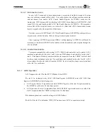
14.3.1.2 5.1 Channel Audio Connection
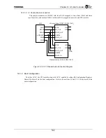
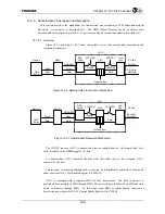
This sample assumes one CODEC with four DACs mapped to stereo front (3&4) and stereo
rear (7&8) slots, and another CODEC with two DACs mapped to center (6) and LFE (9) slots.
Figure 14.3.2 5.1 Channel Audio Connection Diagram
14.3.2 Boot
Configuration
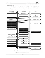
To utilize ACLC, the CPU must boot up with ACLC enabled by setting Pin Configuration Register’s
Shared Pin Select2 via the boot configuration. Refer to the sections 3.2 and 5.2.3 for the detail of the
boot configuration.
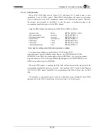
SDIN1
ACRESET
*
BITCLK
SYNC
SDOUT
SDIN0
ACLC
CID0
RESET#
BIT_CLK
SYNC
SDATA_OUT
SDATA_IN
4Channel Audio CODEC (CODEC ID=’0’)
CID1
CID0
RESET#
BIT_CLK
SYNC
SDATA_OUT
SDATA_IN
2Channel Audio CODEC (CODEC ID=‘3’)
CID1
GND
Summary of Contents for TX49 TMPR4937
Page 1: ...64 Bit TX System RISC TX49 Family TMPR4937 Rev 2 0 ...
Page 4: ......
Page 13: ...Table of Contents ix TMPR4937 Revision History 1 ...
Page 14: ...Table of Contents x ...
Page 15: ...Handling Precautions ...
Page 16: ......
Page 18: ...1 Using Toshiba Semiconductors Safely 1 2 ...
Page 40: ...3 General Safety Precautions and Usage Considerations 3 18 ...
Page 42: ...4 Precautions and Usage Considerations 4 2 ...
Page 43: ...TMPR4937 2005 3 Rev 2 0 ...
Page 44: ......
Page 52: ...Chapter 1 Overview and Features 1 6 ...
Page 156: ...Chapter 7 External Bus Controller 7 56 ...
Page 491: ...Chapter 16 Removed 16 1 16 Removed ...
Page 492: ...Chapter 16 Removed 16 2 ...
Page 493: ...Chapter 17 Removed 17 1 17 Removed ...
Page 494: ...Chapter 17 Removed 17 2 ...
Page 495: ...Chapter 18 Removed 18 1 18 Removed ...
Page 496: ...Chapter 18 Removed 18 2 ...
Page 497: ...Chapter 19 Removed 19 1 19 Removed ...
Page 498: ...Chapter 19 Removed 19 2 ...
Page 506: ...Chapter 20 Extended EJTAG Interface 20 8 ...
Page 530: ...Chapter 22 Pinout and Package Information 22 10 ...
Page 542: ...Chapter 24 Parts Number when Ordering 24 2 ...


