Chapter 23 Notes on Use of TMPR4937
23-8
•
Note on use of the PCI boot function
[Restriction]
Don’t perform PCI boot in default setting.
[Violation]
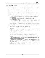
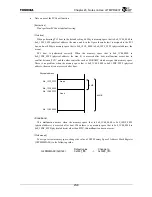
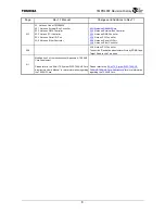
When performing PCI boot in the default setting, 64 Mbyte memory space that is 0x0_1C00_0000 to
0x0_1FFF_FFFF (physical address, the area a and b in the figure shown below) is assigned to the PCI
bus, and not 4 Mbyte memory space that is 0x0_1FC0_0000 to 0x0_1FFF_FFFF (physical address, the
area a).
PCI boot is performed correctly. When the memory space that is 0x0_1C00_0000 to
0x0_1FBF_FFFF (physical address, the area b) is accessed after boot, malfunction occurs due to
conflict between PCIC and the other controller such as SDRAMC which assigns this memory space.
There is no problem when the memory space that is 0x0_1C00_0000 to 0x0_1FBF_FFFF (physical
address, the area b) is not accessed after boot.
<Conditions>
This malfunciton occurs when the memory space that is 0x0_1C00_0000 to 0x0_1FBF_FFFF
(physical address) is accessed after boot. When there is no memory space that is 0x0_1C00_0000 to
0x0_1FBF_FFFF (physical address) other than PCIC, this malfunction does not occur.
[Workaround]
To assign correct memory space, change the value of G2P Memory Space 2 Address Mask Register
(G2PPM2MASK) to the following value.
Default
value
Change
to
G2PM2MASK(0xD148) 0x003f_fff0
->
0x0003_fff0
Area a
4 MB
64 MB
0x0 1C00 0000
0x0_1FFF_FFFF
0x0_1FC0_0000
0x0 1FBF FFFF
Area b
Physical address
Summary of Contents for TX49 TMPR4937
Page 1: ...64 Bit TX System RISC TX49 Family TMPR4937 Rev 2 0 ...
Page 4: ......
Page 13: ...Table of Contents ix TMPR4937 Revision History 1 ...
Page 14: ...Table of Contents x ...
Page 15: ...Handling Precautions ...
Page 16: ......
Page 18: ...1 Using Toshiba Semiconductors Safely 1 2 ...
Page 40: ...3 General Safety Precautions and Usage Considerations 3 18 ...
Page 42: ...4 Precautions and Usage Considerations 4 2 ...
Page 43: ...TMPR4937 2005 3 Rev 2 0 ...
Page 44: ......
Page 52: ...Chapter 1 Overview and Features 1 6 ...
Page 156: ...Chapter 7 External Bus Controller 7 56 ...
Page 491: ...Chapter 16 Removed 16 1 16 Removed ...
Page 492: ...Chapter 16 Removed 16 2 ...
Page 493: ...Chapter 17 Removed 17 1 17 Removed ...
Page 494: ...Chapter 17 Removed 17 2 ...
Page 495: ...Chapter 18 Removed 18 1 18 Removed ...
Page 496: ...Chapter 18 Removed 18 2 ...
Page 497: ...Chapter 19 Removed 19 1 19 Removed ...
Page 498: ...Chapter 19 Removed 19 2 ...
Page 506: ...Chapter 20 Extended EJTAG Interface 20 8 ...
Page 530: ...Chapter 22 Pinout and Package Information 22 10 ...
Page 542: ...Chapter 24 Parts Number when Ordering 24 2 ...


