Chapter 9 SDRAM Controller
9-2
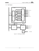
9.2 Block
Diagram
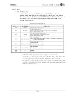
Figure 9.2.1 Block Diagram of SDRAMC
G-Bus
SDRAMC
Channel 0 – 7
Control Register
Timing Register
Command/Load
Register
Refresh Counter
Control
Circuit
G-Bus
Interface
Control
G-Bus
I/F Signal
SDCS [3 : 0]
*
CKE
WE
*
RAS
*
CAS
*
DQM [7 : 0]
CG
SDCLK[3:0]
EBIF
ECC
ADDR [19 : 5]
DATA [63 : 0]
CB [7 : 0]
EBIF
Control Signal
ECC
Control Signal
G-Bus
I/FSignal
ECC
Control Signal
Summary of Contents for TX49 TMPR4937
Page 1: ...64 Bit TX System RISC TX49 Family TMPR4937 Rev 2 0 ...
Page 4: ......
Page 13: ...Table of Contents ix TMPR4937 Revision History 1 ...
Page 14: ...Table of Contents x ...
Page 15: ...Handling Precautions ...
Page 16: ......
Page 18: ...1 Using Toshiba Semiconductors Safely 1 2 ...
Page 40: ...3 General Safety Precautions and Usage Considerations 3 18 ...
Page 42: ...4 Precautions and Usage Considerations 4 2 ...
Page 43: ...TMPR4937 2005 3 Rev 2 0 ...
Page 44: ......
Page 52: ...Chapter 1 Overview and Features 1 6 ...
Page 156: ...Chapter 7 External Bus Controller 7 56 ...
Page 491: ...Chapter 16 Removed 16 1 16 Removed ...
Page 492: ...Chapter 16 Removed 16 2 ...
Page 493: ...Chapter 17 Removed 17 1 17 Removed ...
Page 494: ...Chapter 17 Removed 17 2 ...
Page 495: ...Chapter 18 Removed 18 1 18 Removed ...
Page 496: ...Chapter 18 Removed 18 2 ...
Page 497: ...Chapter 19 Removed 19 1 19 Removed ...
Page 498: ...Chapter 19 Removed 19 2 ...
Page 506: ...Chapter 20 Extended EJTAG Interface 20 8 ...
Page 530: ...Chapter 22 Pinout and Package Information 22 10 ...
Page 542: ...Chapter 24 Parts Number when Ordering 24 2 ...


