Chapter 10 PCI Controller
10-71
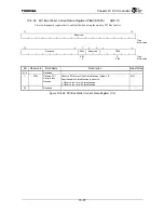
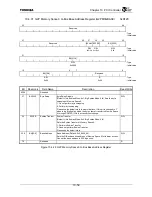
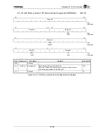
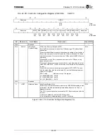
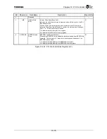
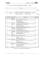
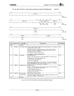
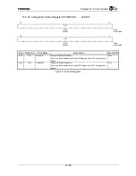
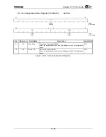
10.4.43 PCI Controller Configuration Register (PCICCFG) 0xD170
31
28
27 16
Reserved GBWC
R/W
:
Type
0xfff
: Initial value
15 12 11 10 9 8 7 6 5 4 3 2 1 0
Reserved HRST
SRST
IRBER
G2PM0EN G2PM1EN G2PM2EN
G2PIOEN
TCAR ICAEN LCFG Reserved
R/W R/W R/W R/W R/W R/W R/W R/W R/W R/W
:
Type
0x0 0x0 0x1 0x0 0x0 0x0 0x0 0x0 0x0 0x0
:
Initial
value
Bit Mnemonic Field
Name
Description
Read/Write
31:28
Reserved
⎯
27:16 GBWC G-Bus Wait
Counter Setting
G Bus Wait Counter (Default: 0xFFF)
Sets the Retry response counter at the G-Bus during a PCI initiator Read
transaction.
When the initiator Read access cycle exceeds the setting of this counter, a
Retry response is sent to the G-Bus and the G-Bus is released. PCI Read
operation continues. This counter uses the G-Bus clock (GBUSCLK) when
operating.
When 0x000 is set, a Retry response is not sent to the G-Bus by a long
response cycle count.
When the G-Bus timeout count is used with the value other than the initial
value 4096 GBUSCLK, G-BUS timeout may occur before a Retry response
is sent.
When G-Bus timeout of the configuration register (CCFG.GTOT) is used
with the value other than the initial value (11), set the following maximum
values to the register.
GTOT value
Maximum value of the register
10 (2048 GBUSCLK) : 0x7f0
01 (1024 GBUSCLK) : 0x3f0
00 ( 512 GBUSCLK) : 0x1f0
R/W
15:12
Reserved
⎯
11
HRST
Hardware Reset
Hard Reset (Default: 0x0)
Performs PCI Controller hardware reset control. EEPROM reloading is also
performed. This bit is automatically cleared when Reset ends. This is a
diagnostic function.
The PCI Controller cannot be accessed for 32 G-Bus clock cycles after this
bit is set.
1: Perform a hardware reset on the PCI Controller.
0: Do not perform a hardware reset on the PCI Controller.
R/W
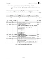
Figure 10.4.41 PCI Controller Configuration Register (1/3)
Summary of Contents for TX49 TMPR4937
Page 1: ...64 Bit TX System RISC TX49 Family TMPR4937 Rev 2 0 ...
Page 4: ......
Page 13: ...Table of Contents ix TMPR4937 Revision History 1 ...
Page 14: ...Table of Contents x ...
Page 15: ...Handling Precautions ...
Page 16: ......
Page 18: ...1 Using Toshiba Semiconductors Safely 1 2 ...
Page 40: ...3 General Safety Precautions and Usage Considerations 3 18 ...
Page 42: ...4 Precautions and Usage Considerations 4 2 ...
Page 43: ...TMPR4937 2005 3 Rev 2 0 ...
Page 44: ......
Page 52: ...Chapter 1 Overview and Features 1 6 ...
Page 156: ...Chapter 7 External Bus Controller 7 56 ...
Page 491: ...Chapter 16 Removed 16 1 16 Removed ...
Page 492: ...Chapter 16 Removed 16 2 ...
Page 493: ...Chapter 17 Removed 17 1 17 Removed ...
Page 494: ...Chapter 17 Removed 17 2 ...
Page 495: ...Chapter 18 Removed 18 1 18 Removed ...
Page 496: ...Chapter 18 Removed 18 2 ...
Page 497: ...Chapter 19 Removed 19 1 19 Removed ...
Page 498: ...Chapter 19 Removed 19 2 ...
Page 506: ...Chapter 20 Extended EJTAG Interface 20 8 ...
Page 530: ...Chapter 22 Pinout and Package Information 22 10 ...
Page 542: ...Chapter 24 Parts Number when Ordering 24 2 ...

