Chapter 8 DMA Controller
8-20
7. Initiate DMA transfer
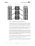
Setting the address of the DMA Command Descriptor at the beginning of the chain list in the DMA
Chain Address Register (DMCHARn) automatically initiates DMA transfer. First, the value stored
in each field of the DMA Command descriptor at the beginning of the Chain List is read to each
corresponding DMA Channel register (Chain transfer), then DMA transfer is performed according
to the read value.
When a value other than “0” is stored in the DMA Chain Address Register (DMCHARn), data of
the size stored in the DMA Count Register (DMCNTRn) is completely transferred, then the DMA
Command Descriptor value of the memory address specified by the DMA Chain Address Register
is read.
In addition, if the Chain Address field value read the Descriptor 0, the DMA Chain Address
Register value is not updated. All previous values (Data Command Descriptor Addresses with the
value “0” in the Chain Address field when the values were read) are held.
0 Value judgement is performed when the lower 32 bits of the DMA Chain Address Register are
rewritten. If the value is not “0” at this time, DMA transfer is automatically initiated. Therefore,
please write to the upper 32 bits first when writing to the DMA Chain Address Register using 32-
bit Store instructions.
8. Signal
completion
Set the Normal Chain End bit (NCHNC) of the DMA Channel Status Register (DMCSRn) when
DMA data transfer of all Descriptor Chains is complete. An interrupt is signalled if the Chain End
Interrupt Enable bit (INTENC) of the DMA Channel Control Register (DMCCRn) is set at this
time.
In addition, the Normal Transfer End bit (NTRNFC) of the DMA Channel Status Register
(DMCSRn) is set each time DMA data transfer specified by each DMA Command Descriptor ends
normally. An interrupt is signalled if the Transfer End Interrupt Enable bit (INTENT) of the DMA
Channel Control Register (DMCCRn) is set at this time.
If an error is detected during DMA transfer, the error cause is recorded in the lower four bits of the
DMA Channel Status register and transfer is interrupted. An interrupt is signalled if the Error
Interrupt Enable bit (INTENE) of the DMA Channel Control Register is set.
8.3.11 Dynamic Chain Operation
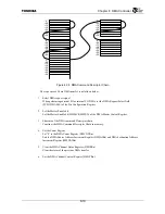
It is possible to add DMA Command Descriptor chains to the DMA Command Descriptor chain
while Chain DMA transfer is in progress. This is performed according to the following procedure.
1. Construct the DMA Command Descriptor chain
Construct the DMA Command Descriptor chain to be added to memory.
2. Add a DMA Command Descriptor chain
Substitute the address of the Command Descriptor at the beginning of the Descriptor Chain to be
added into the Chain Address field of the Descriptor at the end of the DMA Command Descriptor
chain that is currently performing DMA transfer.
3. Check the Chain Enable bit
Read the value of the Chain Enable bit (CHNEN) of the DMA Channel Control Register
(DMCCRn). If that value is “0”, then write the Chain Address field value of the DMA Command
Descriptor that is indicated by the address stored in the DMA Chain Address Register
(DMCHARn).
Summary of Contents for TX49 TMPR4937
Page 1: ...64 Bit TX System RISC TX49 Family TMPR4937 Rev 2 0 ...
Page 4: ......
Page 13: ...Table of Contents ix TMPR4937 Revision History 1 ...
Page 14: ...Table of Contents x ...
Page 15: ...Handling Precautions ...
Page 16: ......
Page 18: ...1 Using Toshiba Semiconductors Safely 1 2 ...
Page 40: ...3 General Safety Precautions and Usage Considerations 3 18 ...
Page 42: ...4 Precautions and Usage Considerations 4 2 ...
Page 43: ...TMPR4937 2005 3 Rev 2 0 ...
Page 44: ......
Page 52: ...Chapter 1 Overview and Features 1 6 ...
Page 156: ...Chapter 7 External Bus Controller 7 56 ...
Page 491: ...Chapter 16 Removed 16 1 16 Removed ...
Page 492: ...Chapter 16 Removed 16 2 ...
Page 493: ...Chapter 17 Removed 17 1 17 Removed ...
Page 494: ...Chapter 17 Removed 17 2 ...
Page 495: ...Chapter 18 Removed 18 1 18 Removed ...
Page 496: ...Chapter 18 Removed 18 2 ...
Page 497: ...Chapter 19 Removed 19 1 19 Removed ...
Page 498: ...Chapter 19 Removed 19 2 ...
Page 506: ...Chapter 20 Extended EJTAG Interface 20 8 ...
Page 530: ...Chapter 22 Pinout and Package Information 22 10 ...
Page 542: ...Chapter 24 Parts Number when Ordering 24 2 ...

