TMPR4937 Revision History
6
Page
Rev 1.1 Manual
Changes and Additions to Rev 1.1
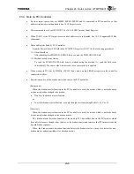
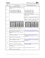
11-22
Figure 11.4.7 Baud Rate Control Register
Modified the description of the BCLK (Baud Rate Generator
Clock) field.
00: Select prescalar output T0 (IMBUSCLK/2)
01: Select prescalar output T2 (IMBUSCLK/8)
10: Select prescalar output T4 (IMBUSCLK/32)
11: Select prescalar output T6 (IMBUSCLK/128)
00: Select prescalar output T0 (
fc
/2)
01: Select prescalar output T2 (
fc
/8)
10: Select prescalar output T4 (
fc
/32)
11: Select prescalar output T6 (
fc
/128)
12-10
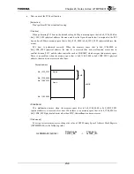
Figure 12.4.1 Timer Control Register
Added the following text to the description of the Counter
Reset Enable field
During CRE = 1, reset the counter if TCE is set from 1 to 0.
During TCE = 0, the counter isn’t reset if CRE is set from 0
to 1.
When TCE = 1 and CRE = 0, stop and reset the counter if
TCE is set to 0 and CRE is set to 1 simultaneously.
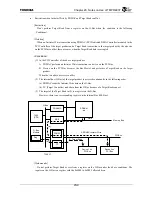
14-11
Table 14.3.7 Mic DMA Buffer Format in Big-endian Mode
Address offset
+0
+1
z #0
H
#0
L
+4 #1
H
#1
L
+8 #2
H
#2
L
: :
:
Address offset
+0
+1
+0
#0
H
#0
L
+4 #1
H
#1
L
+8 #2
H
#2
L
: :
:
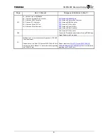
15-5
Modified line 3 of Section 15.3.1,
Interrupt sources
Please refer to the 64-bit TX System RISC TX49/H3 Core
Architecture Manual for more information.
Please refer to the
“64-bit TX System RISC TX49/H2,
TX49/H3, TX49/H4 Core Architecture”
for more information.
20-2
Modified line 2 of Section 20.2.1,
JTAG Controller and
Register
Please refer to the TX49/H3 Core Architecture Manual for
all other portion not covered here.
Please refer to the
“64-bit TX System RISC TX49/H2,
TX49/H3, TX49/H4 Core Architecture”
for all other portion
not covered here.
20-3
Modified line 3 of 20.2.2,
Instruction Register
Refer to the TX49/H3 Core Architecture Manual for more
information regarding each instruction.
Refer to the
“64-bit TX System RISC TX49/H2, TX49/H3,
TX49/H4 Core Architecture”
for more information regarding
each instruction.
20-3
Table 20.2.1 Bit Configuration of JTAG Instruction Register
Refer to the TX49/H3 Core Architecture Manual
Refer to the
“64-bit TX System RISC TX49/H2, TX49/H3,
TX49/H4 Core Architecture”
20-7
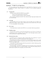
Modified line 5 of Section 20.3,
Initializing the Extended
EJTAG Interface
(Hold the signal low for 2 or more clock cycles of the TCK
input.)
After that, deassert the TRST* signal High.
(TRST
*
signal is pulled down (by ex. 10 k
Ω
))
Summary of Contents for TX49 TMPR4937
Page 1: ...64 Bit TX System RISC TX49 Family TMPR4937 Rev 2 0 ...
Page 4: ......
Page 13: ...Table of Contents ix TMPR4937 Revision History 1 ...
Page 14: ...Table of Contents x ...
Page 15: ...Handling Precautions ...
Page 16: ......
Page 18: ...1 Using Toshiba Semiconductors Safely 1 2 ...
Page 40: ...3 General Safety Precautions and Usage Considerations 3 18 ...
Page 42: ...4 Precautions and Usage Considerations 4 2 ...
Page 43: ...TMPR4937 2005 3 Rev 2 0 ...
Page 44: ......
Page 52: ...Chapter 1 Overview and Features 1 6 ...
Page 156: ...Chapter 7 External Bus Controller 7 56 ...
Page 491: ...Chapter 16 Removed 16 1 16 Removed ...
Page 492: ...Chapter 16 Removed 16 2 ...
Page 493: ...Chapter 17 Removed 17 1 17 Removed ...
Page 494: ...Chapter 17 Removed 17 2 ...
Page 495: ...Chapter 18 Removed 18 1 18 Removed ...
Page 496: ...Chapter 18 Removed 18 2 ...
Page 497: ...Chapter 19 Removed 19 1 19 Removed ...
Page 498: ...Chapter 19 Removed 19 2 ...
Page 506: ...Chapter 20 Extended EJTAG Interface 20 8 ...
Page 530: ...Chapter 22 Pinout and Package Information 22 10 ...
Page 542: ...Chapter 24 Parts Number when Ordering 24 2 ...

