Chapter 10 PCI Controller
10-102
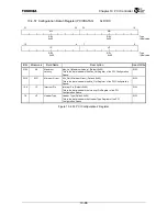
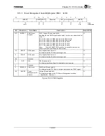
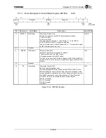
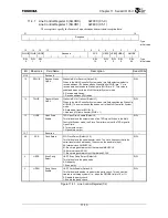
10.5.4 Power Management Control/Status Register (PMCSR) 0xE0
15
14 9 8
7 2 1 0
PMESTA
Reserved
PMEEN
Reserved PS
R/W1C R/W
R/W
:
Type
0x0 0x0
0x0
:
Initial
value
Bit Mnemonic Field
Name
Description
Read/Write
15
PMESTA
PME Status
PME_Status (Default: 0x0)
Indicates the existence of a PME (Power Management Event) .
1: There is a PME.
0: There is no PME.
The value of this bit becomes “1” when Writing a “1” to the PME bit
(P2GCFG.PME) of the P2G Configuration Register.
This bit is cleared when the Host Bridge writes a “1”. It is possible to signal
a PME
*
Clear Interrupt at this time.
R/W1C
14:9
Reserved
⎯
8 PMEEN
PME
Enable PME_En
(Default:
0x0)
Sets PME
*
signal assertion to enable or disable.
1: Enables assertion of the PME
*
signal.
0: Disables assertion of the PME
*
signal.
The PME_En set bit of the P2G Status Register (P2GSTATUS.PMEES) is
set when this bit is set. At this time, it is possible to signal the PME_En set
interrupt.
R/W
7:2
Reserved
⎯
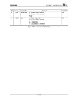
1:0
PS
Power State
PowerState (Default: 0x0)
Sets the Power Management state.
The Power Management State Change bit (P2GSTATUS.PMSC) of the
P2G Status Register is set when the value of this field is changed. It also
becomes possible to generate a Power State Change Interrupt at this time.
The TX4937 can read the value of this field from the PowerState field
(PCISSTATUS.PS) of the Satellite Mode PCI Status Register.
00b: D0 (no change)
01b: D1 :Reserved
10b: D2 :Reserved
11b: D3hot
R/W
Figure 10.5.4 PMCSR Register
Summary of Contents for TX49 TMPR4937
Page 1: ...64 Bit TX System RISC TX49 Family TMPR4937 Rev 2 0 ...
Page 4: ......
Page 13: ...Table of Contents ix TMPR4937 Revision History 1 ...
Page 14: ...Table of Contents x ...
Page 15: ...Handling Precautions ...
Page 16: ......
Page 18: ...1 Using Toshiba Semiconductors Safely 1 2 ...
Page 40: ...3 General Safety Precautions and Usage Considerations 3 18 ...
Page 42: ...4 Precautions and Usage Considerations 4 2 ...
Page 43: ...TMPR4937 2005 3 Rev 2 0 ...
Page 44: ......
Page 52: ...Chapter 1 Overview and Features 1 6 ...
Page 156: ...Chapter 7 External Bus Controller 7 56 ...
Page 491: ...Chapter 16 Removed 16 1 16 Removed ...
Page 492: ...Chapter 16 Removed 16 2 ...
Page 493: ...Chapter 17 Removed 17 1 17 Removed ...
Page 494: ...Chapter 17 Removed 17 2 ...
Page 495: ...Chapter 18 Removed 18 1 18 Removed ...
Page 496: ...Chapter 18 Removed 18 2 ...
Page 497: ...Chapter 19 Removed 19 1 19 Removed ...
Page 498: ...Chapter 19 Removed 19 2 ...
Page 506: ...Chapter 20 Extended EJTAG Interface 20 8 ...
Page 530: ...Chapter 22 Pinout and Package Information 22 10 ...
Page 542: ...Chapter 24 Parts Number when Ordering 24 2 ...

