Official GSK Agents in South Africa
Tel: +27 11 626 2720, [email protected]
Chapter Four Machine Debugging
225
V
o
lume IV
Inst
allation &
Connecti
on
2 8 6
Gear number at the side of the spindle side (the 1
st
shelf gear)
2 8 7
Gear number at the side of the spindle side (the 2
nd
shelf gear)
2 8 8
Gear number at the side of the spindle side (the 3
rd
shelf gear)
Data parameters No.290
~
No.292
2 9 0
Gear number at the side at the encoder side (the 1
st
shelf gear)
2 9 1
Gear number at the side at the encoder side (the 2
nd
shelf gear)
2 9 2
Gear number at the side at the encoder side (the 3
rd
shelf gear)
z
Motion
time-sequence
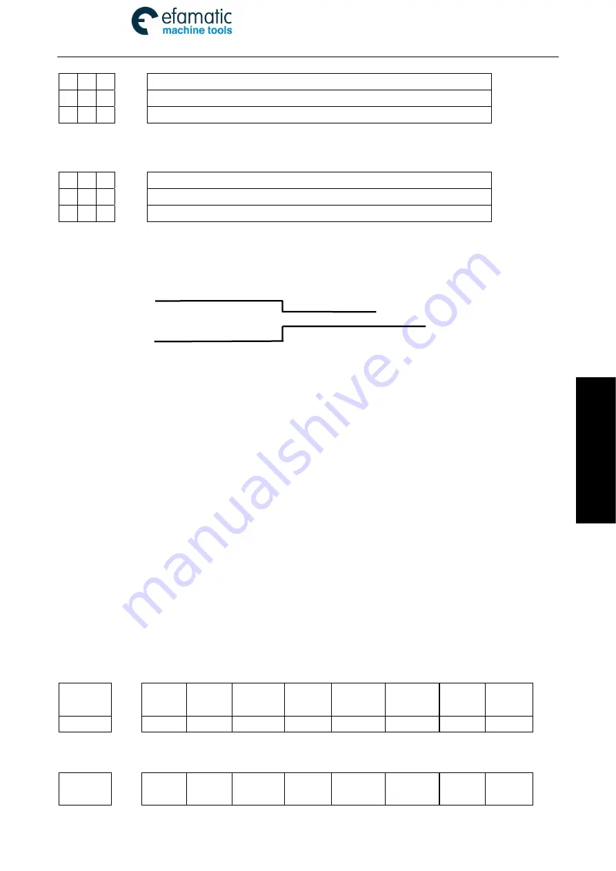
Refer to the Fig. 4-9-1 for the spindle motion time-sequence:
Fig. 4-9-1 Spindle negative time-sequence
z
Control
logic
①
Spindle stops when the system power-on, M05 signal output hold;
②
M3/M4 are enabled and held after performing the M3/M4 codes, and the M05 signal closes to
output;
4.10 Spindle Automatic Gear-shift Control
z
Relative
signal
Y3.4
~
Y3.6: Spindle automatic gear-shift output signal
X4.1
~
X4.3: Spindle gear-shift in-position signal
This system supports 3 shelves spindle automatic gear-shift control and 3 shelves gear-shift
in-position detection function when the spindle frequency-conversion control is performed (0
~
10V
analog voltage output).
z
Signal
diagnosis
Parameter diagnosis (output state at the system side)
State
add.
Y3.6
Y3.5
Y3.4
Pin No.
XS44.25 XS44.12 XS44.24
Y3.4=the spindle gear
I
output
;
Y3.5= the spindle gear
II
output
;
Y3.6= The spindle gear
III
output.
Parameter diagnosis (Input state at the machine side)
State
add.
X4.3 X4.2
X4.1
Spindle
positive/negative
Spindle stop


