background image

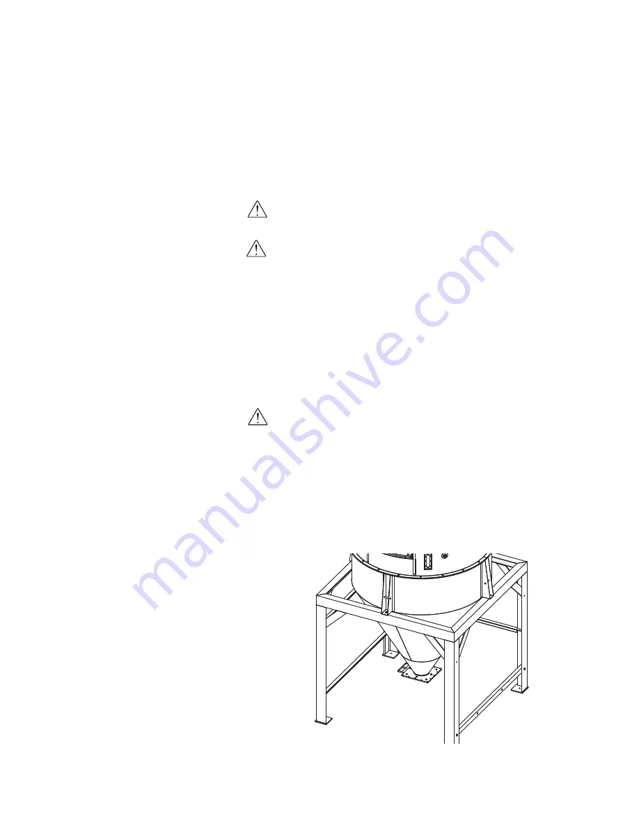
Installing the CH Hopper Cone

Section

Install the hopper cone section on the floor stand using the following steps.

IMPORTANT: 

You will need to consider the location of the CH Hopper’s deliv-

ery air inlet in relation to the dryer installation location for proper setup.

IMPORTANT: 

You will need to consider the location of the HTC heater outlet

in relation to the CH Hopper air inlet location for proper setup.

1

If any hoses, wires, etc. were attached to the floor stand and cone
section

(for shipping purposes), make sure they are positioned away

from the mating surfaces of the assemblies so they will not be damaged
during this procedure.

2

Using a forklift, hoist or crane, lift the cone section assembly above
the floor stand.

CAUTION:  

To prevent accident and injury, lift the cone and hopper sections

onto the floor stand assembly using a forklift, hoist or crane.

3

Set the cone section on the floor stand as shown.

Make sure the holes

in the cone section mounting lugs align with the holes in the top of the
floor stand assembly.

4

Secure the cone section to the floor stand assembly 

using the supplied

hardware.

NOTE:

For EnergySmart Dryer

Systems supplied with "small"
hoppers, the floor stand and cone
section may be pre-assembled at
the factory.  If your floor stand
and cone section are pre-assem-
bled and you have secured the
floor stand to the floor, 

see

Installation section entitled,
Installing the CH Hopper Door,
Upper and Lid Sections.

3-12

l     I n s t a l l a t i o n   -   G e n e r a l

NOTE:

If using carbon steel hop-

pers, be sure to clean out the
hopper prior to use.  Conair
applies a rust inhibitor that must
be removed several hours before
using the hopper.

Summary of Contents for HTC 120

Page 1: ...odels 600 through 5000 with TouchViewTM Technology Allen Bradley Corporate Office 724 584 5500 l Instant Access 24 7 Parts and Service 800 458 1960 l Parts and Service 814 437 6861 U S E R G U I D E UGD041 1212 www conairgroup com ...

Page 2: ...ware Version Number Application File Name Please record your equipment s model and serial number s and the date you received it in the spaces provided DISCLAIMER Conair shall not be liable for errors contained in this User Guide or for incidental consequential damages in connection with the furnishing performance or use of this information Conair makes no warranty of any kind with regard to this i...

Page 3: ...pical applications 2 2 How the EnergySmart Dryer System works 2 3 Specifications EnergySmart Carousel Plus W Series Dehumidifying Dryers 2 4 Hopper Temperature Controller HTC 2 5 GasTrac CGT Process Air Heater 2 6 Dust Collectors 2 7 Positive Displacement PD Pumps 2 8 CH Series Insulated Hoppers 2 9 Drying Monitor DM II Model 2 12 EnergySmart Dryer control options 2 13 3 1 Installation Installatio...

Page 4: ...eceiver s optional 2 25 Installing the purge valve s optional 3 25 Installing the modular distribution box es optional 3 25 Securing the CH hopper to the floor 3 26 Location and mounting of the GasTrac heater 3 27 Location and mounting of the dust collector optional 3 28 Location and mounting of the vacuum pump s and dust collector s optional 3 30 Positioning the dryer on the floor 3 31 Removing t...

Page 5: ...talling the GasTrac RTD sensor 3 48 Installing the return air dew point line 3 49 Installation Main Power Connections 3 51 Connecting main power to the dryer 3 52 Connecting main power to the HTC Models HTC 30 60 90 and 120 3 53 Models HTC 180 and 270 3 54 Connecting main power to the GasTrac 3 56 Connecting main power to the vacuum pump s optional 3 57 Connecting main power to the dust collector ...

Page 6: ... compressed air lines optional 3 86 Installation Gas Piping and Exhaust Flue 3 87 Typical gas line installation drawing 3 88 Installing the Conair GasTrac 3 89 Connecting the gas and the exhaust flue to the GasTrac 3 92 Installation Testing 3 95 Checking for proper air flow 3 96 Testing the variable frequency drive VFD 3 99 Testing the installation of the HTC 3 100 Checking the gas and electrical ...

Page 7: ...rt 4 13 Example setpoint change 4 14 Control function descriptions 4 15 EnergySmart Dryer System security levels 4 54 EnergySmart Dryer System Modbus communications 4 56 Starting the EnergySmart Dryer System Without OptiMizer mode 4 58 Adjusting the EnergySmart Dryer System Without OptiMizer mode 4 62 Starting the EnergySmart Dryer System With OptiMizer mode 4 67 Stopping the EnergySmart Dryer Sys...

Page 8: ... of the GasTrac 5 15 Cleaning the process filter 5 17 Cleaning the regeneration filter 5 18 Cleaning the aftercooler intercooler coils 5 19 Cleaning the volatile trap on the demister W600 1000 5 21 Cleaning the volatile trap on the demister W1600 5000 5 22 Cleaning the precooler coils optional 5 23 Replacing the regeneration heater W600 1000 5 24 W1600 2400 5 26 W3200 5000 5 28 Checking dew point ...

Page 9: ...ays 6 35 Checking or replacing temperature sensors 6 36 Replacing the desiccant wheel assembly W600 1000 6 37 Replacing the desiccant wheel motor W600 1000 6 39 Replacing the desiccant wheel motor W600 1000 6 40 A Appendix We re here to help A 1 How to contact customer service A 1 Before you call A 1 Equipment guarantee A 2 Performance warranty A 2 Warranty limitations A 2 Conair print numbers lis...

Page 10: ...viii l Table of Contents ...

Page 11: ...he guide is organized 1 2 Using the EnergySmart Dryer with your system 1 3 Your responsibilities as a user 1 3 ATTENTION Read this so no one gets hurt 1 4 How to use the lockout device 1 6 S E C T I O N 1 Introduction l 1 1 1 I n t r o d u c t i o n ...

Page 12: ...een used to help organize the User Guide and call your attention to important information regarding safe installation and operation Symbols within triangles warn of conditions that could be hazardous to users or could damage equipment Read and take precautions before proceeding Numbers indicate tasks or steps to be performed by the user A diamond indicates the equipment s response to an action per...

Page 13: ...with all safety procedures concerning installation opera tion and maintenance of this equipment Responsible safety procedures include Thorough review of this User Guide paying particular attention to hazard warnings appendices and related diagrams Thorough review of the equipment itself with careful attention to voltage sources intended use and warning labels Thorough review of instruction manuals...

Page 14: ...ound Do not operate the equipment at power levels other than what is specified on the machine serial tag and data plate WARNING Voltage hazard This equipment is powered by three phase alternating current as specified on the equipment s serial tags and data plates Reference optional additional equipment s manuals for their power requirements A properly sized conductive ground wire from the incoming...

Page 15: ...ide the dryer and hopper Also exercise caution around exterior surfaces that may become hot during use These include the hopper door frame the exterior of an uninsulated hopper the return air hose and the dryer s process filter housing and exhaust outlet and the Hopper Temperature Controller HTC or GasTrac Dryer CGT WARNING Do not place aerosol compressed gas or flammable materials on or near this...

Page 16: ...tured below To use the lockout device 1 Stop or turn off the equipment 2 Isolate the equipment from the electric power Turn the rotary disconnect switch to the OFF or O position 3 Secure the device with an assigned lock or tag Insert a lock or tag in the holes to prevent movement 4 The equipment is now locked out WARNING Before removing lockout devices and returning switches to the ON position mak...

Page 17: ...ecifications EnergySmart Carousel Plus W Series Dehumidifying Dryers 2 4 Hopper Temperature Controller HTC 2 5 GasTrac CGT Process Air Heater 2 6 Dust Collectors 2 7 Positive Displacement PD Pumps 2 8 CH Series Insulated Hoppers 2 9 Drying Monitor DM II Model 2 12 EnergySmart Dryer control options 2 13 S E C T I O N 2 2 D e s c r i p t i o n ...

Page 18: ...er with an integrated cyclone optional Heater gas or electric Dust collector s optional Patented DM II drying monitor technology Receiver s optional Vacuum pump s optional Audible alarm Typical Applications 1 Dryer on the floor a single CH Hopper with a Hopper Temperature Controller HTC or GasTrac Dryer CGT package on a floor stand The EnergySmart Dryer System can be used successfully in applicati...

Page 19: ...of a CH Hopper The air moves up through the hopper picking up moisture from the material as it transfers its heat into the material Once the air is at the top of the hopper it returns to the dryer after passing through optional filtration to remove fines Once in the dryer the air is cooled by passing through a cooling coil to lower the temperature so that the air can be dried as it passes through ...

Page 20: ...y a Hopper Temperature Controller HTC or GasTrac Dryer CGT When to use additional filtration The standard return air cartridge filter is sized for the airflow of each dryer model and is suited for most applications You should consider adding an optional dust collector and or volatile trap if The material contains excessive fines An additional dust collector or cyclone will extend time between filt...

Page 21: ...nozzle 10 6 7 1 8 0 10 0 13 0 15 4 below the heater box 26 9 18 0 20 3 25 4 33 0 39 1 Installed weight lb kg 38 17 37 17 78 35 93 43 102 46 131 59 Control center dimensions Height F 24 0 61 0 24 0 61 0 36 0 91 4 48 0 122 0 60 0 152 4 60 0 152 4 Width G 24 0 61 0 24 0 61 0 30 0 76 2 36 0 91 4 42 0 106 7 42 0 106 7 Depth H 10 0 25 4 10 0 25 4 10 0 25 4 10 0 25 4 12 0 30 5 12 0 30 5 Clearance for hea...

Page 22: ...h 29 737 37 940 37 940 37 940 37 940 C Length 66 1676 64 1626 74 1880 74 1880 74 1880 Air inlet outlet OD 8 203 8 203 8 203 8 203 12 300 Approximate weight lb kg Installed 600 272 600 272 600 272 600 272 600 272 Shipping 700 317 700 317 700 317 700 317 600 272 Voltage Total amps 380V 3 phase 50Hz 3 0 3 0 1 6 1 3 3 0 415V 3 phase 50Hz 3 0 2 7 1 5 1 2 3 0 240V 3 phase 60Hz 3 0 4 8 2 5 2 0 3 0 480V 3...

Page 23: ...stics Pump size range Hp kW 3 7 5 2 2 5 6 10 25 7 5 18 7 Vacuum line size OD in mm 1 5 2 5 38 1 63 5 2 25 4 0 57 2 101 6 Filter area ft2 M2 42 8 4 0 100 3 9 3 Maximum collection capacity ft3 liters 1 1 31 1 2 1 59 4 Recommended dust collection ft3 liters 0 75 21 2 1 0 28 3 Dimensions inches cm A Height 58 0 147 3 67 0 170 1 B Width 15 0 38 1 19 0 48 3 Depth 20 0 50 8 19 0 48 3 Weight lb kg Install...

Page 24: ... 5 29 5 575 2 9 4 8 7 5 10 7 16 27 Energy saving high efficiency motors are also available Specifications Positive Displacement PD Pumps MODELS PD3 PD5 PD7 5 PD10 PD15 PD25 SUPER ANY MODEL Performance Average Sound Level dbA 8 10 and 12 Hg 61 9 69 8 76 2 79 3 86 0 90 0 Under 60 dbA Enclosure Construction Painted Steel Natural Aluminum Painted Steel Allowance Space for Service Access in 48 Opposite...

Page 25: ...Specifications CH Series Insulated Hoppers Without Integrated Cyclone Fig 1 A B C D E With Integrated Cyclone Fig 2 A B A D E Description l 2 9 2 D e s c r i p t i o n TPDS006 0408 REV ...

Page 26: ...IB09 IB09 IB09 IB09 IB09 IB09 MODEL CH74 245 CH74 366 CH74 487 CH100 450 CH100 675 CH100 900 FIGURE NUMBER Fig 1 Fig 1 Fig 1 Fig 1 Fig 1 Fig 1 Performance characteristics Capacity ft3 liter 245 6938 366 10365 487 13792 450 12743 675 19114 900 25485 Capacity 35 lb ft3 8575 12810 17045 15750 23625 31500 Dimensions inches cm A Inside diameter 74 188 74 188 74 188 100 254 100 254 100 254 B Hopper heig...

Page 27: ...45 96 4 245 96 4 245 96 4 245 96 4 245 101 8 259 101 8 259 101 8 259 101 8 259 E Depth 96 4 245 96 4 245 96 4 245 96 4 245 96 4 245 101 8 259 101 8 259 101 8 259 101 8 259 Air inlet OD 8 20 3 8 20 3 Air outlet OD 8 20 3 8 20 3 Material discharge ID 6 15 2 6 15 2 Approximate weight lb kg Installed weight hopperandcyclone 1650 748 1800 816 2000 907 2100 953 2200 998 2400 1089 2600 1179 2700 1225 280...

Page 28: ... package includes Drying monitoring probe Connecting cable Pre wired dryer panel Light tower Specifications Drying Monitor DM II Model SPECIFICATION NOTES Specifications can change without notice Check with a Conair representative for the most current information Drying Hopper Conair Part CH 54 70 1819080140 CH 54 85 1819080141 CH 54 99 1819080142 CH 54 114 1819080123 CH 54 129 1819080143 CH 64 15...

Page 29: ...yer system Recipe storage screen The recipe storage screen is used to store and instantly recall specific dryer parameters that are used with different types of material Up to 99 dryer recipes can be saved within the control Loading control screens Dedicated screens control the function and activation of up to two 2 optional receivers Loading dump and purge times can be individually altered for ea...

Page 30: ...2 14 l Description ...

Page 31: ...3 12 Installing the CH hopper door upper and lid sections 3 13 Installing the cyclone optional 3 17 Installing the drying monitor probe 3 22 Installing the receiver s optional 3 25 Installing the purge valve s optional 3 25 Installing the modular distribution box s optional 3 25 Securing the CH hopper to the floor 3 26 Location and mounting of the GasTrac heater 3 27 Location and mounting of the d...

Page 32: ...nnecting the dryer to the heat source 3 39 Connecting the dust collector optional 3 40 Connecting the cyclone separator optional 3 41 Installing the Dwyer 641 air velocity transmitter 3 42 Installing the level switch optional 3 44 Adjusting the level sensor optional 3 45 Installing the process protection RTD sensor 3 46 Location of the process material temperature probe RTD 3 47 Installing the Gas...

Page 33: ...cuum pump s and dust collector s optional 3 61 Installation Water Lines 3 63 Typical water lines installation drawing 3 64 Connecting the aftercooler intercooler and optional precooler W600 1000 3 65 Connecting the aftercooler intercooler and optional precooler W1600 5000 3 66 Installation Control and Communications Wiring 3 67 Connecting the HTC to the HTC controller 3 68 Connecting the RTD senso...

Page 34: ...aust flue to the GasTrac 3 92 Installation Testing 3 95 Checking for proper air flow 3 96 Testing the variable frequency drive VFD 3 99 Testing the installation of the HTC 3 100 Checking the gas and electrical systems of the GasTrac 3 102 Testing the installation of the GasTrac 3 103 Testing the primary receiver optional 3 105 Testing the secondary receiver optional 3 107 Configuring the Dwyer 641...

Page 35: ...Installation General Installation General l 3 5 3 I n s t a l l a t i o n ...

Page 36: ...ove the component from the pallet With a forklift hoist or crane carefully move the components to their approximate installation locations 2 Remove all packing material protective paper tape and plastic including any inserted inside the components 3 Carefully inspect all components to ensure no damage occurred during ship ping and that you have all the necessary hardware If any damage is found not...

Page 37: ... Dryer System for the weights of each component A source of water for the aftercooler intercooler or optional pre cooler of the dryer The water source must be tower city or chiller water at temperatures of 45 to 85 F 7 to 29 C Refer to the speci fications supplied with your system for the flow rate Piping should be installed to the dryer location Flexible hose can be used to connect the water pipe...

Page 38: ...nce Due to the varying size of Conair CH Hoppers Conair recommends Following all applicable local building and safety codes 1 Make sure the installation location for the CH Hopper meets all provisions for clearances will support the weight of the fully loaded hopper and provides space for the installation of the other system components such as optional receivers See the specifications and drawings...

Page 39: ...the left side of the CH Hopper floor stand on models 30 60 and 90 NOTE If by using your own provisions you change the mounting arrangement of the control center to a wall mount unit it must be mounted 6 inches 152 4 mm off of the wall to provide clearance for the heat sink HTC Control Center continued NOTE If using a GasTrac for the drying system heat source see Installation section entitled Insta...

Page 40: ...location for operation see figure to the right The control center must be posi tioned close enough to the hopper to allow connection of the RTD temperature probe The control center can be mounted to a wall the hopper frame or a floor stand with customer supplied provisions NOTE If by using your own provisions you change the mounting arrangement of the con trol center to a wall mount unit it must b...

Page 41: ...Use the locking fasteners provided to securely mount the heater assembly to the floor stand to prevent vibration induced loosening NOTE The heater is prewired to the control box on HTC Model 120 Location and Mounting of the HTC Heater Assembly Models HTC 180 and 270 CAUTION You are responsible for the structural integrity of this installation 1 Securely bolt the HTC heater assembly to the back of ...

Page 42: ... stand CAUTION To prevent accident and injury lift the cone and hopper sections onto the floor stand assembly using a forklift hoist or crane 3 Set the cone section on the floor stand as shown Make sure the holes in the cone section mounting lugs align with the holes in the top of the floor stand assembly 4 Secure the cone section to the floor stand assembly using the supplied hardware NOTE For En...

Page 43: ...e before making the installation permanent Hopper Door Section To install the hopper door section of the CH Hopper 1 Apply sealer around the lip on the top of the cone section 2 Using a forklift hoist or crane lift the hopper door section assembly above the cone section CAUTION To prevent accident and injury lift the hopper door section onto the cone section using a forklift hoist or crane NOTE Wh...

Page 44: ... door section on the cone section as shown As the hopper door section is positioned on the cone section make sure the holes in the hopper door section align with the holes in the cone section 4 Secure the hopper door section to the cone section using the supplied hardware 3 14 l Installation General continued ...

Page 45: ... As the hopper upper section is positioned on the hopper door section make sure the holes in the upper section align with the holes in the door section 4 Secure the hopper upper section to the hopper door section using the supplied hardware NOTE If more than one 1 hopper upper section is to be installed repeat the steps detailed in this section for each hopper upper section NOTE When applying the ...

Page 46: ...d section align with the holes in the hopper door or hopper upper section 4 Secure the hopper lid section to the hopper door or hopper upper section using the supplied hardware CAUTION To prevent accident and injury lift the hopper lid section onto the hopper door or hopper upper sections using a forklift hoist or crane NOTE When applying the sealer do not cover the holes in the upper section lip ...

Page 47: ...our system setup 2 Remove the five 5 bolts located on the top of the lid of the hopper The removal of the five 5 bolts is dependent upon the installation location of the cyclone 3 Remove the five 5 bolts located on the hopper upper section or hopper door section of the hopper The removal of the five 5 bolts is dependent upon the installation location of the cyclone CAUTION To prevent accident and ...

Page 48: ...ten the bolts the cyclone installation may need to be adjusted for hard piping of the cyclone s inlet and outlet ports 7 Locate the three 3 90 degree pieces of tubing These pieces will connect the CH Hopper to the cyclone 8 Bolt two 2 of the pieces of 90 degree tubing together using the supplied hardware Be sure to place the supplied gasket between the two 2 pieces of tubing before tightening the ...

Page 49: ...en the two 2 pieces of tubing before tighten the tube bolts 10 Loosely bolt the now finished tubing assembly to the CH Hopper s return air outlet and to the cyclone s air inlet using the supplied hardware Be sure to place the supplied gaskets between the tubing assembly and the CH Hopper outlet and cyclone air inlet before tightening bolts Mounting location is dependent upon the installation locat...

Page 50: ...14 Bolt the 45 degree piece of tubing to the outlet of the cyclone using the supplied hardware Be sure to place the supplied gasket between the tubing and the cyclone outlet before tightening bolts Mounting orientation is depend ent upon your system s configuration 15 Bolt the straight piece of tubing to the assembly in Step 14 using the sup plied hardware Be sure to place the supplied gasket betw...

Page 51: ...f tubing installed in Step 15 using the supplied hose clamp 18 Route the hose to the waste container Make sure all hoses are securely clamped to prevent wasteful leaking The hoses should be routed neatly and supported where possible to prevent undue stress on cyclone assembly 19 Connect the hosing to the waste container s lid using the supplied hose clamp NOTE Do not allow the flexible hoses to ki...

Page 52: ...lid section into the hopper with the tip of the probe approximately in line with the bottom edge of the dry air spreader cone 4 Push the compression sleeve into the fitting 5 Tighten the nut over the sleeve The com pression sleeve will crimp the tube to hold the probe in place Be sure to position the connec tor on the DM probe in such a way as to avoid interference with cables receiver etc Use an ...

Page 53: ...sket over the probe hole 5 Place the adapter plates over the gas ket and secure them to the hopper with three 3 10 32 UNF screws Make sure the adapter plate with the threaded hole is on the bottom and that the slots in the adapter plates are ori ented in the opposite direction as shown See the drawing on the next page 6 Secure the coupling to the adapter plates with the four 4 10 32 UNF screws 7 S...

Page 54: ... compression sleeve will crimp the tube to hold the probe in place Be sure to position the connector in such a way as to avoid interference of the cable with the receiver etc Use an appropriately sized wrench to tighten the nut so that it covers the threads 7 Gasket 4 Sleeve Coupling Hopper Nut Fitting Adapter plate Threaded adapter plate 5 6 9 10 3 24 l Installation General ...

Page 55: ...ottom of the CH Hopper or auxiliary hop per follow the installation instructions specifications and wiring diagrams sup plied with the valve Also refer to the purge valve s installation instructions and operations manual for power compressed air connections specifications Installing the Modular Distribution Box es optional If a modular distribution box is to be mounted to the bottom of the CH Hopp...

Page 56: ...nair CH Hoppers Conair recommends Following all applicable local building and safety codes Using anchoring techniques and hardware suitable for the size and weight of a fully loaded CH Hopper See Description section entitled Specifications CH Series Insulated Hoppers 1 Secure the floor stand to the floor following all applicable building and safety codes NOTE The footpads on the floor stand have e...

Page 57: ...xhaust flue can be connected easily IMPORTANT You will need to consider the location of the CH Hopper s delivery air inlet and the dryer installation location to properly install the GasTrac 3 Secure the GasTrac to the mounting location floor using the holes in the base of the GasTrac Check to ensure that the mounting method meets all local regional and national codes and regulations NOTE Electric...

Page 58: ...e CH Hopper and optional integrated cyclone IMPORTANT You will need to consider the installation of your entire dryer system before permanently placing any system component CAUTION To prevent accident and injury move the dust collector to its mounting location using a forklift hoist or crane 2 Secure the dust collector to the mounting location on the floor by using the holes in the legs of the dus...

Page 59: ... become detached from the dust collector s inlet and outlet tubes during installation NOTE Electrical control and air flow connections to the dust collector will be covered later in the installation process NOTE Dust collector shown with straight legs Your EnergySmart Dryer system will be supplied with dust collectors with kick out legs Installation General l 3 29 Pressure Differential Transmitter...

Page 60: ...ump s and associat ed dust collector s to their locations by using a forklift hoist or crane 2 Position the equipment so that the main power supply communication cables and conveying lines can be connected easily IMPORTANT You will need to consider the location of all EnergySmart Dryer System components to properly install the vacuum pump s and associated dust collector s 3 Secure the vacuum pump ...

Page 61: ...he cable tie securing the desiccant wheel if it was not done while unpacking the dryer Installing the Regeneration Exhaust Cover The EnergySmart Dryer s regeneration exhaust cover must be installed before using the dryer To install the regeneration exhaust cover 1 Remove the exhaust cover that is attached to the dryer s shipping pallet 2 Locate the bolt pattern on the top of the dryer over top of ...

Page 62: ...urn air inlet 3 Position the return air adapter over top of the return air inlet aligning both bolt patterns 4 Secure the return air adapter with supplied hardware using an appropriately sized wrench Return Air Inlet Adapter 3 32 l Installation General NOTE If your system has hard piping use the instructions in the next section An optional hard piping kit for your EnergySmart Dryer system is avail...

Page 63: ...nd dry air outlet 3 Position the return air adapter over top of the return air inlet aligning both bolt patterns 4 Secure the return air adapter with supplied hardware using an appropriately sized wrench 5 Position the dry air outlet adapter over top of the dry air outlet aligning both bolt patterns 6 Secure the dry air outlet adapter with supplied hardware using an appropriately sized wrench Dry ...

Page 64: ...with included gaskets 2 2 Locate the bolt patterns on the top of the dryer over top of the overhead process air duct inlet and outlet 3 Position the overhead process air duct over top of the overhead process air duct inlet and outlet making sure to place supplied gaskets between the overhead process air duct and the inlet and outlet of the dryer align all bolt patterns 4 Secure the piping with sup...

Page 65: ...Installation Hard Piping Kits Installation Piping Hoses l 3 35 3 I n s t a l l a t i o n ...

Page 66: ...th 8 inch and 12 inch 203 2 and 304 8 mm hard piping kits that can be used for your EnergySmart Dryer System installation For more informa tion concerning hard piping kits contact your Conair Representative 3 36 l Installation Piping Hoses An optional hard piping kit for your EnergySmart Dryer system is available from Conair Contact Conair Parts 800 458 1960 From outside of the United States call ...

Page 67: ...hose is used make sure it is securely clamped Make sure all hoses are securely clamped to prevent wasteful leaking The hoses should be routed neatly and supported where possible to prevent undue stress on the heater and hopper assemblies Also the bends should be made with gradual radiuses Sharp turns will cause undue pressure drops HTC Outlet to CH Hopper Inlet Connection Installation Piping Hoses...

Page 68: ...are securely clamped to prevent wasteful leaking The hoses should be routed neatly and supported where possible to prevent undue stress on the heater and hopper assemblies Also the bends should be made with gradual radiuses Sharp turns will cause undue pressure drops NOTE Do not allow the flexible hoses to kink or crimp An optional hard piping kit for your EnergySmart Dryer system is available fro...

Page 69: ...ported where possible to prevent undue stress on the heater and hopper assemblies Also the bends should be made with gradual radiuses Sharp turns will cause undue pressure drops Installation Piping Hoses l 3 39 Dryer Connection to HTC Shown HTC Inlet Dryer Outlet NOTE Do not allow the flexible hoses to kink or crimp 3 I n s t a l l a t i o n An optional hard piping kit for your EnergySmart Dryer s...

Page 70: ...hoses should be routed neatly and supported where possible to prevent undue stress on the heater and hopper assemblies Also the bends should be made with gradual radiuses Sharp turns will cause undue pressure drops Dust Collector Outlet Dryer Inlet NOTE Do not allow the flexible hoses to kink or crimp 3 40 l Installation Piping Hoses An optional hard piping kit for your EnergySmart Dryer system is...

Page 71: ...e routed neatly and supported where possible to prevent undue stress on the heater and hopper assemblies Also the bends should be made with gradual radiuses Sharp turns will cause undue pressure drops Outlet to Dust Collector Inlet from Cyclone NOTE Do not allow the flexible hoses to kink or crimp 3 I n s t a l l a t i o n Installation Piping Hoses l 3 41 An optional hard piping kit for your Energ...

Page 72: ...o straighten out before it comes in contact with the probe Placing the probe too close to a transition or bend will influence air flow readings To install the AVT 1 Determine the best location to install the AVTs following the recommendations above 2 If Conair s hard piping kit was not purchased with your system drill and tap customer supplied 8 or 12 in 203 2 or 304 8 mm 2 ft 0 6 m long pipe with...

Page 73: ...ed to secure the transmitter is pointing in the direction of the air flow The arrow is located on the nut below the conduit bodies 5 Center in pipe This will allow you to adjust the air velocity probe in the cen ter of the air stream Air Flow Direction Arrows Located on the Nut 3 I n s t a l l a t i o n Installation Piping Hoses l 3 43 NOTE Refer to Dwyer 641 Instructions found in the Appendix of ...

Page 74: ...d Allen wrench Several port plugs are located along the side of the CH Hopper 2 Locate the level switch 3 Apply Teflon tape to the installation threads of the level switch 4 Insert the level switch into the material port selected in Step 1 5 Install the level switch by rotating the probe and engaging the threads in Step 3 using an appropriately sized wrench 6 Connect the wiring to the level switch...

Page 75: ...ust turns OFF If the course potentiometer has been carefully adjusted this should occur when the fine potentiometer is between the 8 and 10 o clock positions Now continue to turn the FINE potentiometer clockwise to the desired sensitivity setting High sensitivity 1 16 turn Medium sensitivity 1 8 turn Low sensitivity 1 4 to 1 2 turn IMPORTANT The calibra tion potentiometers are delicate electronic ...

Page 76: ...erates an alarm on the HTC control panel A 49 or A 50 and shuts the heater off if the air temperature exceeds the process protection setpoint The element for this sensor is to be mounted in the heater assembly outlet nozzle before the insulat ed hose is connected 1 Insert the process protection RTD probe into the heater assembly outlet nozzle Center the end of the probe in the outlet so that the t...

Page 77: ... of the machine to which your mate rial is being delivered for an existing tap location that can be used to mount the RTD If none exists a second option is to incorporate RTD mounting capabilities into the piping flange that will connect to the bottom of the CH Hopper after the slide gate Conair recommends locating the RTD probe when possible within 30 ft 9 15 m of the EnergySmart Dryer NOTE If th...

Page 78: ...temperature readings will be inaccu rate 1 Insert the probe into the air inlet port of the CH Hopper The end of the probe must not touch the walls of the inlet pipe 2 Tighten the compression fitting to lock the RTD probe in place 3 Route the GasTrac RTD cable towards the location of the GasTrac control panel RTD Probe 3 48 l Installation Piping Hoses ...

Page 79: ...o 4 ft 0 9 to 1 2 m copper tube to the dew point line fitting Route the copper tube down towards the EnergySmart Dryer The copper tube is needed to dissi pate heat from the sample air 3 Connect the supplied Teflon tubing to the end of the copper tube using the compression fit ting supplied Route the Teflon tubing towards the Return Air Dew Point fitting on the back of the EnergySmart Dryer 4 Cut t...

Page 80: ...3 50 l Installation Piping Hoses ...

Page 81: ...3 I n s t a l l a t i o n Installation Main Power Connections Installation Main Power Connections l 3 51 ...

Page 82: ...or open 2 Insert the main power wire through the knockout in the side of the enclo sure or the rear of the dryer the dryer s electrical wire connection location was a factory option and may be connected through the front or the rear of the dryer Secure the wire with an appropriately sized strain relief 3 Connect the power wires to the three 3 terminals at the top of the power disconnect holder 4 C...

Page 83: ...ons Electrical connections should be made only by a qualified technician CAUTION Check the disconnect with a volt meter to ensure that the power is off 1 Disconnect and lock out the main power before making electrical connec tions Electrical connections should be made only by a qualified technician 2 Turn the disconnect dial on the control center door to the Off or O position Turn the captive scre...

Page 84: ...ons should be made only by a qualified technician 2 Turn the disconnect dial on the control center door to the Off or O position Turn the captive screw and swing the control center door open 3 Insert the main power cable through a knockout in the side of the control center Secure the power cable with an appropriately sized strain relief or use customer supplied conduit Verify that the incoming pow...

Page 85: ... and heater ground wire to the ground lug as shown 8 Insert the other end of heater power wire through the knockout in the side of the heater assembly Secure the wire with an appropriately sized strain relief if conduit is not used 9 Connect the heater power wires to the top terminals of the heater assem bly s terminal block and heater ground wires to the ground lug as shown Power Wires Gray Custo...

Page 86: ...th an appro priately sized relief 3 Connect the power wires to the three 3 terminals at the top of the disconnect holder 4 Connect the ground wire to either grounding point shown in the dia gram Honeywell ESC SEL IMPORTANT Always refer to the wiring diagrams that came with the GasTrac before making electrical connections CAUTION Electrical Hazard Always disconnect and lock out the main power sourc...

Page 87: ...t is specified on the the machine serial tag and data plate 2 Check for proper rotation of the pump after power has been connected and before operation Connecting Main Power to the Dust Collector s optional Proper operation of the optional dust collector depends upon its internal vacuum valve opening whenever the vacuum pump is energized Electrical connections are provided by a 3 conductor cable c...

Page 88: ...3 58 l Installation Piping Hoses ...

Page 89: ...3 I n s t a l l a t i o n Installation Main Power Connections l 3 59 Installation Conveying Lines ...

Page 90: ...iver is to be used follow the instructions supplied with the receiver to connect the conveying lines Also refer to the receiver s installation instructions and operations manual for power level switch and compressed air connections specifications Connecting the Conveying Lines to the Purge Valve s optional If a purge valve is to be mounted to the bottom of the CH Hopper or auxiliary hop per follow...

Page 91: ... optional receiver dust collector and vacu um pump are to be used Make sure all hoses are securely clamped to prevent wasteful leaking The hoses should be routed neatly and supported where possible to prevent undue stress Also the bends should be made with gradual radiuses Sharp turns will cause undue pressure drops Air Inlet Air Outlet Collection Chamber Floor Stand To Material Supply NOTE Vacuum...

Page 92: ...3 62 l Installation Conveying Lines ...

Page 93: ...Installation Water Lines 3 I n s t a l l a t i o n Installation Water Lines l 3 63 ...

Page 94: ...FOR EASIER REMOVAL OF CONDENSER SEE INDIVIDUAL UNIT SPECIFICATION SHEET FOR UNIT SPECIFIC SIZES CUSTOMER HARD PLUMB WATER CONNECTION 3 64 l Installation Water Lines Typical Water Lines Installation Drawing Conair recommends providing supply and return water valves at this location ...

Page 95: ...urn line with the pressure relief valve to the aftercooler intercooler or precooler outlet Use the bracket supplied to secure the pressure relief valve to the back of the dryer IMPORTANT Turn the water off when the dryer is not in use to prevent condensation Aftercooler Intercooler Inlet Aftercooler Intercooler Outlet TIP Make the water supply and dis charge return connections with flexible hoses ...

Page 96: ...outlet Use the bracket supplied to secure the pressure relief valve to the back of the dryer IMPORTANT Turn the water off when the dryer is not in use to prevent condensation Aftercooler Intercooler Inlet Aftercooler Intercooler Outlet TIP Make the water supply and dis charge return connections with flexible hoses at least 24 in 61 cm long This allows you to easily remove the aftercooler intercool...

Page 97: ...Installation Control Communication Wiring 3 I n s t a l l a t i o n Installation Control Communication Wiring l 3 67 ...

Page 98: ... of the control wires through the knockout in one side of the HTC heater assembly terminal box Secure with a appropriately sized strain relief if conduit is not used 5 Connect the high temperature and pressure switch wires to the heater assembly terminal block IMPORTANT The connection between the heater and control center should be made with customer supplied wire that has properly sized conductor...

Page 99: ...ires to the control center s terminal block and heater ground wire to the ground lug as shown 8 Insert the other end of heater power wire through the knockout in the side of the heater assembly Secure the wire with an appropriately sized strain relief if conduit is not used 9 Connect the heater power wires to the top terminals of the heater assem bly s terminal block and heater ground wires to the...

Page 100: ...to the HTC s control panel Plug the connector into receptacle in the side of the control center labeled Process Hand tighten the connector Coil any excess cable and secure it with a wire tie Process Protection RTD Probe The process protection RTD probe is a safety sensor that prevents the HTC s heater from overheating in case of a process temperature sensor failure or insulated hose failure The pr...

Page 101: ...ions should be made only by qualified personnel 1 Disconnect and or lock out main power to the HTC 2 Route the process protection RTD cable from hopper inlet to the HTC control panel Plug the connector into the recepta cle in the side of the control center labeled Process Protection Hand tighten the con nector Coil any excess cable and secure it with a wire tie ON O OFF IMPORTANT Always refer to t...

Page 102: ...elec trical connections Electrical connections should be made only by qualified personnel 1 Disconnect and or lock out main power to the GasTrac 2 Route the GasTrac RTD cable to the GasTrac control center 3 Plug the RTD cable into the GasTrac control center Coil any excess cable and secure with a wire tie NOTE Conair recommends locat ing the RTD probe when possible within 30 ft 9 15 m of the GasTr...

Page 103: ...to the receptacle in the top of the probe 2 Route the DM cable from the DM probe to the side of the EnergySmart Dryer s electrical enclosure 3 Connect the DM cable to the DM cable receptacle on the side of the EnergySmart Dryer s electrical enclosure IMPORTANT Always refer to the wiring diagrams that came with your Drying Monitor before making electrical connec tions DM Cable Connection at the Pro...

Page 104: ...ide and indicates to a receiver that a load cycle is required If the probe is not installed correctly material level readings will be inaccurate CAUTION Always disconnect and lock out the main power sources before making elec trical connections Electrical connections should be made only by qualified personnel IMPORTANT Always refer to the wiring dia grams that came with your optional level switch ...

Page 105: ...ations inter connecting wiring The control system inter connecting wiring consists of 24 VDC connections neces sary for the EnergySmart Dryer control to operate the system components The communications inter connecting wire is a typical Modbus 485 daisy chain used to read data from system components NOTE The communications interconnecting daisy chain wire starts at its connection point at the Ener...

Page 106: ...ation section entitled Connecting the EnergySmart Dryer Control to System Components HTC As Heat Source CAUTION Always disconnect and lock out the main power sources before making electrical connections Electrical connections should be made only by qualified personnel 1 Disconnect and or lock out main power to the EnergySmart Dryer and the GasTrac 2 Open the door of the EnergySmart Dryer electrica...

Page 107: ... port in the GasTrac s electrical enclosure for the control system inter connecting and the communication inter connecting wires 9 If not using conduit drill or cut the entry ports one for the inter connect ing wire and one for the communication inter connecting wire 10 If not using conduit insert the control system inter connecting and the communications inter connecting wires for the GasTrac thr...

Page 108: ...communication inter connecting wire 3b If using electrical conduit cut entry ports for both wires and then run customer supplied conduit for each from the EnergySmart Dryer s electrical enclosure to the HTC s electrical enclosure 4 Route the control system inter connecting and communications inter con necting wires from the EnergySmart Dryer electrical panel to the HTC electrical panel 5 If not us...

Page 109: ...he communication inter connecting wire 10 If not using conduit insert the control system inter connecting and the communications inter connecting wires for the HTC through their respected entry ports on the HTC s electrical enclosure Secure the wires with an appropriately sized strain relief 11 Connect the control system inter connecting wires to the HTC s electrical panel as detailed in the suppl...

Page 110: ...onnections Electrical connections should be made only by qualified personnel To connect the AVT to the EnergySmart Dryer electrical panel 1 Disconnect and or lock out main power to the EnergySmart Dryer 2 Route the wires from the AVT to the EnergySmart Dryer electrical panel 3 Determine the location of the entry port on EnergySmart Dryer s electri cal panel for the AVT wires Open the door of the E...

Page 111: ...ySmart Dryer system electrical panel using the 3 wire receiver negative common diagram as shown The receiver in this case is the Allen Bradley 1762 IF4 analog input card Refer to your Dwyer 641 Manual for more detail 3 WIRE RECEIVER NEGATIVE COMMON DC SUPPLY ONLY EITHER POLARITY RECEIVER IMPORTANT Always refer to the wiring diagrams that came with your AVT and EnergySmart Dryer before making elect...

Page 112: ...g electrical conduit cut entry port and then run customer supplied conduit from the EnergySmart Dryer s electrical enclosure to the vacuum pump 4 Insert the pump wires through the entry port on the dryer s control panel Secure the wires with an appropriately sized strain relief 5 Connect the wiring to vacuum pump as detailed in the supplied wiring diagram 6 Connect the wiring of the vacuum pump to...

Page 113: ...b If using electrical conduit cut the entry port and then run customer sup plied conduit from the EnergySmart Dryer s electrical enclosure to the receiver 5 If using electrical conduit insert the wiring for the receiver through the entry port on the dryer s electrical panel Secure the wires with an appro priately sized strain relief 6 Connect the wiring to receiver as detailed in the supplied wiri...

Page 114: ... 3 Open the door of the EnergySmart control panel and determine the location of the entry port on the dryer s control panel for the control system inter connecting wires of the air pressure sensor 4 Drill or cut the entry port 4b If using electrical conduit cut the entry port and then run customer supplied conduit from the EnergySmart Dryer s electrical enclosure to the sensor 5 If using electrica...

Page 115: ...Installation Compressed Air Lines 3 I n s t a l l a t i o n Installation Compressed Air Lines l 3 85 ...

Page 116: ...pressed air lines Also refer to the compo nent s installation instructions and operation manuals for power and compressed air connections specifications EnergySmart Dryer System components that require compressed air Receiver s Adjustable Purge Valve APV or Pocket valve Knife gate s Dust collector s with conveying circuits 3 86 l Installation Compressed Air Lines ...

Page 117: ...Installation Gas Piping and Exhaust Flue GasTrac only 3 I n s t a l l a t i o n Installation Gas Piping and Exhaust Flue l 3 87 ...

Page 118: ...LLATION 3 88 l Installation Gas Piping and Exhaust Flue B ONTRACTOR HRENHEIT DETAIL B SCALE 1 5 GAS CONNECTION BEFORE CONNECTION INSTALL A DROP TEE AS SHOWN USING A CAP AND 8 NIPPLE SEE INDIVIDUAL UNIT SPECIFICATION SHEETS FOR UNIT SPECIFIC SIZE AND TYPE ION Typical Gas Line Installation Drawing 399 DEG CELSIUS ...

Page 119: ...r is required to obtain the proper delivery gas pressure 1 to 5 psig the regulator must have an ANSI Class 6 positive shut off to pre vent gas pressure increase when the GasTrac is turned off The following chart is a listing of the maximum gas usage and inlet line size used on each GasTrac GasTrac Model Max Gas Flow CFH CMH Inlet Line Size NPT CGT150 150 4 2 3 4 in CGT250 250 7 1 3 4 in CGT350 350...

Page 120: ...e not exceeded the CFM CMH of the combustion exhaust should be checked prior to the addition of the exhaust stack After adding the exhaust stack the CFM CMH should be rechecked to ensure that the air flow is within the guidelines The GasTrac should not be ran for long periods of time without being properly connected to the exhaust ducting directing flue products to a suitable point exiting the bui...

Page 121: ...onair recommends using condensation traps as necessary For every 1 000 cubic feet 28 3 cubic meters of gas burned 6 gallons 22 7 L of water vapor will be produced in the flue gases If the flue gas temperature drops below 212 F 100 C the vapor in the flue will condense to water Installation Gas Piping and Exhaust Flue l 3 91 ...

Page 122: ...e the flue and exhaust T assembly Exhaust flue and T tempera tures can reach up to 750 F 399 C 4 Install a condensate trap and drain Condensate occurs when flue gases cool below their dew point This condensate can be highly corrosive Draining and disposal should be done in compliance with applicable safety and environmental codes in your area Flue T Pipe V Clamp Condensate Drain Exhaust Outlet WAR...

Page 123: ...ge the gas lines after the pipe and fittings are free of leaks The lines must be free of air rust scale pipe dope and welding slag Gas Supply Inlet Gas Inlet Fitting Sizes Model NPT size CGT150 3 4 in CGT250 3 4 in CGT350 3 4 in CGT500 3 4 in CGT700 1 in 3 I n s t a l l a t i o n NOTE Conair strongly recom mends that a drop tube be utilized when piping the gas line into the GasTrac This will help ...

Page 124: ...3 94 l Installation Gas Piping and Exhaust Flue ...

Page 125: ...Installation Testing 3 I n s t a l l a t i o n Installation Testing l 3 95 ...

Page 126: ...ryer Doors W1600 5000 To unlock the side panel door bolts 1 Rotate the two 2 locking door bolts on the dryer door counterclockwise with a regular screw driver 2 Close the dryer doors and rotate the two 2 locking door bolts clockwise to resecure the dryer doors Testing for Proper Rotation 1 Turn on the main power to the dryer Make sure the dryer s disconnect dial is in the ON position This powers u...

Page 127: ...difying Drying Screen Screen 6 5 Visually verify the blower motor is moving in the correct direction indicat ed by the arrow on the blower housing The EnergySmart W series 600 5000 dryers are equipped with centrifugal process blow ers Remember to also check the regen blower on ES1 WARNING All wiring disconnects and fuses should be installed by qualified electrical tech nicians in accordance with e...

Page 128: ... the dryer WARNING All wiring disconnects and fuses should be installed by quali fied electrical technicians in accordance with electrical codes in your region Always maintain a safe ground Do not operate the equipment at power levels other than what is specified on the machine serial tag and data plate ON O OFF WARNING All wiring disconnects and fuses should be installed by qualified electrical t...

Page 129: ...direction of rotation and air flow 3 Press the Start button to bring the process blower up to speed Watch for anything unusual such as vibration overheating of bearings and motor etc 4 Check the blower s motor amperage against the nameplate amperage to ensure that the motor is not overloading The amperage is shown on the display screen 5 Press the Stop button once the blower has been tested and is...

Page 130: ...l components are securely mounted Make sure all hoses are connected to the proper locations and secured with hose clamps Make sure all sensors are properly installed and secured Make sure all wiring is secure and away from potential mechanical damage Make sure the hopper outlet is free from obstructions that would cause back pressure in the drying hopper 5 Start the EnergySmart Dryer see Installat...

Page 131: ...e dryer see Operation section entitled Stopping the EnergySmart Dryer System Heaters Startup Shutdown For Startup 1 With heaters in Standby turn on blower or dryer 2 Enable heaters For Shutdown 1 Switch heaters to Standby 2 Wait 60 seconds before turning off blower or dryer Enable Standby NOTE When testing the HTC process protection should be enabled in the HTC s Control menu This is especially im...

Page 132: ...as supply to the GasTrac Open the primary gas shutoff valve Use a gas leak detection device or a squirt bottle of soapy water to detect leaks around gas pipe and fitting joints Open the secondary gas shutoff valve and continue checking for leaks using the same procedure WARNING Ensure all gas lines are free of leaks To prevent accident or injury all gas lines including the GasTrac s factory mounte...

Page 133: ...tiation which ends when the display indicates STANDBY 5 Set the drying temperature Press the up or down arrow on the temperature controller until 250 F appears in the lower display 6 Press the RUN button The green RUN light will illuminate after the Burner Controller finishes initializing The combustion blower will start and run for 90 seconds to purge any residual gas from the burner Check blower...

Page 134: ...ure to reach setpoint 9 Once the setpoint is reached press the STOP button The green RUN indicator light turns off The gas inlet valves should close The combustion blower should stop The burner and temperature controllers should display STANDBY 10 After the test has been completed successfully turn off the power to the GasTrac allow to cool and properly shut down the dryer see Operation section en...

Page 135: ...al supply hose of the optional receiver at the source 3 Login to the EnergySmart Dryer control under the appropriate user name and password See Operation section entitled Control Function Descriptions Screen 1A Login Screen 4 Navigate to the System Overview Screen Screen 6 5 Press the receiver s magnifying glass icon to access the Primary Loader Screen Screen 5 continued ...

Page 136: ...e of the receiver will open at the end of the load cycle time for the duration of the dump time set at this screen 7 Press the Disable button on the Primary Hopper Loader Screen Screen 5 to deactivate the primary receiver If everything is installed correctly the following sequence should occur The Positive Displacement Pump will turn off unless idle mode equipped The discharge valve of the receive...

Page 137: ... at the source Bottom of primary hopper 3 Login to the EnergySmart Dryer control under the appropriate user name and password See Operation section entitled Control Function Descriptions Screen 1A Login Screen 4 Navigate to the System Overview Screen Screen 6 5 Press the Secondary Loader button to access the Secondary Loader Screen Screen 18 continued NOTE Secondary loader must have been enabled i...

Page 138: ...f the receiver will open at the end of the load cycle time for the duration of the dump time set at this screen 7 Press the Disable button on the Secondary Hopper Loader Screen Screen 18 to deactivate the secondary receiver If everything is installed correctly the following sequence will occur The Positive Displacement Pump will turn off unless idle mode equipped The discharge valve of the receive...

Page 139: ...llowing the range selec tion instructions within the Dwyer Series 641 Air Velocity Transmitter Specifications Installation and Operating Instructions that are sup plied with the EnergySmart Dryer System The measuring range will change based on the blower size 5 Set the range of theAVT into the Engineering Maximum input field for the appropriate flow transmitter See Operation section entitled Contr...

Page 140: ...rature RTD is selected the control will alert the operator if the appropriate drying temperature is not reached within four 4 hours default time NOTE If a change is made to the HTC or GasTrac the DM II will need to be reset For more infor mation refer to the supplied DM II User s manual Configuring the Level optional The optional level switch sensor monitors the amount of material inside the CH Ho...

Page 141: ... CH Hopper If you have mounted an optional vacuum receiver on the hopper disconnect the material inlet hose at the source 2 Turn on the main power to the dryer and the HTC or GasTrac Be sure that the dryer s disconnect dial is in the ON position This powers up the touch screen control Check to make sure that the HTC Enable switch is on if applicable 3 From the Login Screen Screen 1 press the Syste...

Page 142: ...t wheel does not turn verify that the desiccant wheel tie has been removed The loader and pump will come on if supplied and if loaders enabled 5 From the System Control Screen Screen 16 press the Stop System button If everything is installed correctly The blowers will process and continue running as needed to cool the heaters until regeneration heaters are less than 150 F 66 C 6 The test is over I...

Page 143: ...s setup flow chart 4 13 Example setpoint change 4 14 Control function descriptions 4 15 EnergySmart Dryer System security levels 4 54 EnergySmart Dryer System Modbus communications 4 56 Starting the EnergySmart Dryer System Without OptiMizer mode 4 58 Adjusting the EnergySmart Dryer System Without OptiMizer mode 4 62 Starting the EnergySmart Dryer System With OptiMizer mode 4 67 Stopping the Energ...

Page 144: ...enters the user name and password access is permitted to the Login Setup screen Screen 1B From this screen the user depending on security access level can access the various system and setup screens for the entire EnergySmart Dryer system The following two sections provide flowcharts that detail the navigation between the EnergySmart Dryer Control screens and provide a description of the function ...

Page 145: ...ons Touching the magnifying glass icons will take the user to screens that contain detailed information about the system com ponent selected continued Navigation Buttons Touching the navigation buttons will take the user to the control screen selected Operation l 4 3 NOTE Some buttons may be grayed out indicating that an option is not installed or the user does not have access to those functions ...

Page 146: ...pop up keyboard window that appears when an appropriate field is touched Set points can be entered within fields with a heavy black boundaries Values shown within colored boxes are actual values and can not be changed Set Point Field User Changeable Actual Values Non Changeable continued NOTE Password required for changing setpoints ...

Page 147: ... is to be selected from a list of parameters the Up and Down arrows can be used to highlight the selection Press the Enter button to activate the selection Enter Button Up and Down Arrows Operation l 4 5 NOTE The values shown in the data fields indicate the values entered when last updated ...

Page 148: ...4 6 l Operation Control Function Flow Charts Login Flow Chart 1A 1B continued NOTE Depending on your user login level some functions may not be available ...

Page 149: ...4 O p e r a t i o n Operation l 4 7 Control Function Flow Charts continued Operation Flow Chart 1 1A 2 3 4 continued 5 ...

Page 150: ...4 8 l Operation Control Function Flow Charts continued Operation Flow Chart 2 1A 18 16 6 7 8 14 15 17 continued These screens are optional ...

Page 151: ...4 O p e r a t i o n Operation l 4 9 Control Function Flow Charts continued Operation Flow Chart 3 8 9 10 11 12 13 continued These screens are optional ...

Page 152: ...Control Function Flow Charts continued Setup Flow Chart 1 1B 19 38 20 34 37 4 10 l Operation continued ...

Page 153: ...4 O p e r a t i o n Control Function Flow Charts continued Equipment Setup Flow Chart 1 20 25 23 22 26 24 21 Operation l 4 11 continued These screens are optional ...

Page 154: ...Control Function Flow Charts continued Equipment Setup Flow Chart 2 20 27 33 32 28 29 30 31 4 12 l Operation continued These screens are optional ...

Page 155: ... p e r a t i o n Control Function Flow Charts continued Communications Setup Flow Chart 34 36 35 Operation l 4 13 continued NOTE Login must be pressed to return to the System Overview in the setup screens ...

Page 156: ...l Operation Control Function Flow Charts continued Example Set Point Change NOTE Only white background boxes with numbers in them can be changed Other color boxes are actual readings with no setpoint values ...

Page 157: ... the Login button This provides access to the User Password window When either the User or Password buttons are pressed a pop up keyboard window appears that allows the user to enter their user name or password NOTE From the Login screen a user can navigate through all of the EnergySmart Dryer Control screens without logging onto the system However the user will not be able to change any setpoints...

Page 158: ... or password has been entered 3 Press the Enter button again to access the Login Setup screen Screen 1B Screen 1B Login Setup The Login Setup screen allows the user to access the system parameter screens by press ing the Setup button on the bottom right side of the screen continued NOTE The Setup button is not available with Operator login ...

Page 159: ...rmation provided by this screen includes the temperature at var ious levels within the hopper as well as temperatures dew points differential pres sures and air flow rates of the air circulating within the system The user can also view the other system parameters start the system stop the system initiate a system Cool Down or return to the Login screen by pressing the applicable buttons on the rig...

Page 160: ...een The user can also view the other system parameters start the system stop the system initiate a system Cool Down or return to the Login screen by pressing the applicable buttons on the right of the screen NOTE Screen 3 shows the type of heater installed in the Dehumidifying Drying Circuit of the EnergySmart Dryer System If a GasTrac has been installed the image on the screen will reflect a gas ...

Page 161: ...etpoints If the user is logged in at the proper security level the regeneration temperature dew point air flow high air flow alarm and the low air flow alarm setpoints can be changed on this screen This screen also allows the user to start or stop the dryer and select between auto or manual control for the dryer blower The user can also view the other system parame ters start the system stop the s...

Page 162: ...ess the Enabled button to activate the primary receiver Pressing the Disabled button will de activate the receiver The receiver s current status will be displayed under the receiver s icon in the top left side of this screen The user can also view the other system parameters start the system stop the system initiate a system Cool Down or return to the Login screen by pressing the applicable button...

Page 163: ... to start or stop the heater or dryer and lists the delivery air temperature the air flow at the dryer and the differential pressure alarm setpoints If the user is logged in at the proper security level the deliv ery air temperature air flow at the dryer and differential pressure alarm setpoints can be changed from this screen The user can also view the other system parameters start the system sto...

Page 164: ...he proper security level the process material high and low temperature alarm setpoints can be changed on this screen The DM Trending button on this screen gives the user instant access to the Material Temperature Trending screen Screen 9 The user can also view the other system parameters start the system stop the system initiate a system Cool Down or return to the Login screen by pressing the appl...

Page 165: ...nding screen The choices are Material Temperature Temp Screen 9 Air Flow Screen 10 Air Temperature Temp Screen 11 Dew Point Screen 12 Differential Pressure Screen 13 To select the specific type of trending screen press the appropriate button on the Trending screen The user can also view the other system parameters start the system stop the system initiate a system Cool Down or return to the Login ...

Page 166: ...ed with the locations are Orange Process Material Temperature Exiting the hopper Red DM Probe Temp 1 hopper cone Yellow DM Probe Temp 2 Blue DM Probe Temp 3 Purple DM Probe Temp 4 Dark Green DM Probe Temp 5 Light Green DM Probe Temp 6 Top of hopper The Material Temperature Trending screen shows a snap shot of the last two 2 hours of opera tion and records and saves trending data for the last 72 ho...

Page 167: ...the dehumidi fying drying circuit on this graph The Air Flow Trending screen shows a snap shot of the last two 2 hours of operation and records and saves trending data for the last 72 hour period The scroll buttons near the bottom of the screen allow the user to scroll back to an earlier time or forward to the present time plus jump to the present time from any time within the trending record The ...

Page 168: ...Temperature Blue Hopper Outlet Temperature Purple Dewpoint trending screen Light Green Dry Air Heater On Time Orange Regeneration Temperature within the Dryer The Air Temp Trending screen shows a snap shot of the last two 2 hours of opera tion and records and saves trending data for the last 72 hour period The scroll but tons near the bottom of the screen allow the user to scroll back to an earlie...

Page 169: ...are Red Process Dew point Yellow Return Air Dew point Purple Return Air Temp Wheel Desiccant Inlet Orange Regeneration Temperature within the Dryer The Dew Point Trending screen shows a snap shot of the last two 2 hours of opera tion and records and saves trending data for the last 72 hour period The scroll buttons near the bottom of the screen allow the user to scroll back to an earlier time or f...

Page 170: ...is associated with the Filter Optional Dust Collector Differential Pressure The Differential Pressure Trending screen shows a snap shot of the last two 2 hours of operation and records and saves trending data for the last 72 hour period The scroll buttons near the bottom of the screen allow the user to scroll back to an earlier time or forward to the present time plus jump to the present time from...

Page 171: ...background colors are associated with the types alarms Red Active Alarm Yellow Acknowledged Alarm Black Inactive Alarm For more detailed information concerning the EnergySmart Dryer alarms see Troubleshooting section The scroll buttons on the right of the screen allow the user to scroll up or down though the alarm events or jump to the top or bottom of the alarm log Near the bot tom right of the s...

Page 172: ... their materi al Temperature setpoints and air flows can be configured to change an existing recipe or create a new recipe delete a recipe and upload a recipe depending upon the appli cation See Operation section entitled Using Dryer Recipes Scroll buttons on the right side of the recipe windows allow the user to scroll through recipes and their individual parameters Press the Close button to exit...

Page 173: ...r Mode by pressing the associated buttons The user can also view the other system parameters start the system stop the system initiate a system Cool Down or return to the Login screen by pressing the applicable buttons on the right of the screen NOTE Set points boxes are white with heavy black borders Set points can be changed if the user has logged in at the proper securi ty level by pressing the...

Page 174: ...nction Pressing the Disarmed button will de activate Auto Start The Auto Start function s current status will be displayed on the right side of this screen The user can also view the other system parameters start the system stop the system initiate a system Cool Down or return to the Login screen by pressing the applicable buttons on the right of the screen NOTE Set points boxes are white with hea...

Page 175: ...ton to activate the optional secondary receiver Pressing the Disabled button will de activate the receiver The receiver s current status will be displayed under the receiver s icon in the top left side of this screen The user can also view the other system parameters start the system stop the system initiate a system Cool Down or return to the Login screen by pressing the applicable buttons on the...

Page 176: ...ection will be indicated by a yellow triangle 2 Press the Enter button to lock in the current selection To update change the dryer control s clock 1 Press the appropriate box under its heading Use the pop up keyboard win dow to enter the new time and date and press the Enter key to lock in the time 2 Press the Update button to update the control s clock NOTE Set points boxes are white with heavy b...

Page 177: ...Each button navigates the user to additional setup screens Dry Air Setup VFD PID Setup Ethernet Setup Options Setup Instrument 1 2 and 3 Setup Regen PID Setup Loader Setup Primary Test Outputs OptiMizer Setup Close HMI Loader Setup Secondary if applicable The user can also view the other system parameters start the system stop the system initiate a system Cool Down or return to the Login screen by...

Page 178: ...System none GasTrac or Electric the dryer cool down method model number of the heat booster and the dryer model number To configure the EnergySmart Dryer System 1 Use the up and down arrow buttons to make the appropriate selection The current selection will be indicated by a yellow triangle 2 Press the Enter button to lock in the current selection The user can also view the other system parameters...

Page 179: ...oint and the deadband set points If the user is logged in at the proper security level all setpoints contained on this screen can be changed using the pop up keypad window The user can also view the other system parameters start the system stop the system initiate a system Cool Down or return to the Login screen by pressing the applicable buttons on the right of the screen NOTE The air flow setpoi...

Page 180: ...in the current selection 4 Repeat Steps 1 3 for each address 5 Cycle the dryer s power after all changes are complete The user can also view the other system parameters start the system stop the system initiate a system Cool Down or return to the Login screen by pressing the applicable buttons on the right of the screen NOTE Set points boxes are white with heavy black borders Set points can be cha...

Page 181: ...ding not installed or installed recipe storage not installed or installed Allen Bradley ethernet not installed or installed primary loader not installed or installed and secondary loader not installed or installed The user can also view the other system parameters start the system stop the system initiate a system Cool Down or return to the Login screen by pressing the applicable buttons on the ri...

Page 182: ...aled Output Units If the user is logged in at the proper security level all setpoints contained on this screen can be changed using the pop up keypad window The user can also view the other system parameters start the system stop the system initiate a system Cool Down or return to the Login screen by pressing the applicable buttons on the right of the screen NOTE Set points boxes are white with he...

Page 183: ...s of the regeneration circuit If the user is logged in at the proper security level all setpoints contained on this screen can be changed using the pop up keypad window The user can also view the other system parameters start the system stop the system initiate a system Cool Down or return to the Login screen by pressing the applicable buttons on the right of the screen NOTE Set points boxes are w...

Page 184: ...contained on this screen include Raw Input mA Engineering Minimum Engineering Maximum Offset Scaled Output Units If the user is logged in at the proper security level all setpoints contained on this screen can be changed using the pop up keypad window NOTE Set points boxes are white with heavy black borders Set points can be changed if the user has logged in at the proper security level by pressin...

Page 185: ...up screen allows the user to enable or disable the optional receiver and to choose the type of purge valve working with the receiver To select the type of valve 1 Use the up and down arrow buttons to make the selection The current selection will be indicated by a yellow triangle 2 Press the Enter button to lock in the current selection The user can also view the other system parameters start the s...

Page 186: ...sable the optional receiver and to choose the type of purge valve working with the receiver To select the type of valve 1 Use the up and down arrow buttons to make the selection The current selection will be indicated by a yellow triangle 2 Press the Enter button to lock in the current selection The user can also view the other system parameters start the system stop the system initiate a system C...

Page 187: ... Drying Monitor Temperature T1 Hopper Outlet Return Air Temperature Where applicable the settings and data contained on this screen include Offset Scaled Output Units If the user is logged in at the proper security level all setpoints contained on this screen can be changed using the pop up keypad window NOTE Set points boxes are white with heavy black borders Set points can be changed if the user...

Page 188: ...d settings are deviation values above or below the Material Temperature Target Set points See Operation section entitled Using the OptiMizer The user can also view the other system parameters start the system stop the system initiate a system Cool Down or return to the Login screen by pressing the applicable buttons on the right of the screen NOTE Set points boxes are white with heavy black border...

Page 189: ...tial power up start screen To restart the EnergySmart Dryer s control interface 1 Press twice on the FactoryTalkView ME Icon 2 Touch the Load Application button 3 Select the application Typically it is the only application listed 4 Press the Load button 5 When prompted Do you want to replace the terminal s current communica tion configuration with the application s communication press the No but t...

Page 190: ...ater Stop Loader 2 Material Alarm light Red Vacuum pump 2 Alarm horn To test an output first press the Test Mode Disable button to change to test mode enabled 1 Press the button of the output to be tested The output will turn on and remain on until the button is pressed again The user can also view the other system parameters start the system stop the system initiate a system Cool Down or return t...

Page 191: ...t side of the Main Setup Screen Screen 19 The Comms Setup screen allows the user to access the Read and Write Date Communications Setup Screens Screens 35 and 36 by pressing the appropriate button The user can also view the other system parameters start the system stop the system initiate a system Cool Down or return to the Login screen by pressing the applicable buttons on the right of the screen...

Page 192: ...Air Blower Dry Air GasTrac Gas Heater Only Dry Air Burner Gas Heater Only Dry Air Electric HB HTC Only Turbo Blower Turbo Electric HB This screen also allows the user to see the error count for each communications func tion the Comms Communications Retry Counter setpoint and to reset the error counters Reset Error CT button for the dehumidifying drying circuit If the user is logged in at the prope...

Page 193: ...able the data write function indicated by a green LED or Disable the data write function indicated by a red LED with the following components within the EnergySmart System by pressing the applicable buttons Dry Air GasTrac setpoint Gas Heater Only Dry Air Electric HB setpoint HTC Only Turbo Electric HB setpoint The user can also view the other system parameters start the system stop the system ini...

Page 194: ...proper security level all setpoints contained on this screen can be changed using the pop up keypad window The user can also view the other system parameters start the system stop the system initiate a system Cool Down or return to the Login screen by pressing the applicable buttons on the right of the screen NOTE Set points boxes are white with heavy black borders Set points can be changed if the...

Page 195: ...rying Monitor Temperature T1 If the user is logged in at the proper security level all setpoints contained on this screen can be changed using the pop up keypad window The user can also view the other system parameters start the system stop the system initiate a system Cool Down or return to the Login screen by pressing the applicable buttons on the right of the screen NOTE Set points boxes are wh...

Page 196: ...sentative The following table and accompanying text gives an overview of the security levels and description of the functions available at each level DEFAULT Default Level A Start and stop at the system level Start and stop individual equipment OPER Operator Levels A B Change date and time Start and stop at the system level Start and stop individual equipment Change operating setpoints Change alar...

Page 197: ...pervisor Levels A B C Change date and time Start and stop at the system level Start and stop individual equipment Change operating setpoints Change alarm setpoints Go into setup menus Add equipment in the setup menus Instrument setup Variable frequency drive setup Shutdown RSView Close HMI Recipes ...

Page 198: ... are communicated via the programmable logic controller PLC located in the control panel EnergySmart Component Node Address Dryer Variable Frequency Drive VFD 5 Dry Air GasTrac Single Loop Temperature Controller TC 7 Dry Air GasTrac Flame Controller FC 8 Dry Air Electric HTC 9 Turbo Blower 11 Turbo Electric HB 12 continued ...

Page 199: ... failed is put back into the poll list when the Alarm Acknowledge button is pressed on the Alarm Log Screen Screen 14 or after 300 seconds by the Communications Comms Retry Timer Each individual message command can be disabled by a Supervisor on the Read Data Communication screen Screen 35 This could be necessary if there is a failure of the communications hardware on a par ticular component When ...

Page 200: ...icon Once at the Primary Loader Screen Screen 5 set the receiver s load time dump time and purge times and press the Enable button to start loading the CH Hopper 2b If not using the loading function fill the CH Hopper with material 3 Navigate to the Dehumidifying Dryer Screen Screen 4 within the dryer s control 4 Set the dehumidifying drying circuit air flow to Manual mode 5 Set the air flow setpo...

Page 201: ...midifying Drying Circuit of the EnergySmart Dryer System If a GasTrac has been installed the image on the screen will reflect a gas heater flame If an HTC has been installed the image on the screen will reflect an electric heater heating coil The screen used in this example reflects an electric heater heating coil NOTE Set points boxes are white with heavy black borders Set points can be changed i...

Page 202: ...de 8 Navigate to the System Control Screen Screen 8 after all setpoints have be entered and log out 9 Press the Start System button to begin pre drying your material 10 Navigate to the Material Temperature Trending Screen Screen 9 It may take a few hours to gather trending data continued ...

Page 203: ...ns a steady state approximately 4 to 6 hours 12 Start the injection processing extrusion machine after the normal pre dry time is complete approximately 4 to 6 hours The injection machine will begin taking material out of the hopper As the system is running it will take several hours for all components to reach a steady state running condition Conair recommends waiting until the system is in a con...

Page 204: ...e air flow from Manual mode to Automatic mode CFM setpoint the control will automatically set the CFM setpoint to be equal to the value it was running as a percentage The same is true when switching from Automatic mode to Manual mode The control will set the equal to the value it was running as a setpoint This is done so that the system is not interrupted when changing the air flow control mode Yo...

Page 205: ... Screen 7 in the hopper to stabilize based on a change in air flow The change in air flow will also affect the return air temperature Increasing air flow will also increase the hopper outlet temperature It is common to see changes in air flow based on the optional receiver dumping material into the top of the hopper This is due to changes in the system pres sure when the receiver valve opens This ...

Page 206: ... will see this by an increase in blower speed to maintain the same air flow setpoint if in Auto This is normal and will change back once the processing machine begins to take material from the hopper again If in Manual you may experience a reduction in airflow Temperature Electric Hopper Temperature Controllers HTCs There is one heater for the dry air loop supplied with the EnergySmart Dryer Syste...

Page 207: ...ntain the required material throat temperature In situations where the incoming material moisture content is low 1000 ppm or less Winter you will be able to run lower setpoint temperatures Changes to setpoint temperatures will affect the material temperature profile and the hopper outlet temperature continued NOTE Making too large of a change in setpoint will change the material throat tempera tur...

Page 208: ...addition to what is described in the Temperature Electric Hopper Temperature Controllers HTCs section the GasTrac heater will have limited turndown capability The operating range is affected by how low the flame can turned down For example as the air flow setpoint is lowered the GasTrac will automatically adjust turn down the flame to maintain the same setpoint tem perature Eventually the GasTrac ...

Page 209: ...5 set the receiver s load time dump time and purge times and press the Enable button to start loading the CH Hopper 2b If not using the loading function fill the CH Hopper with material 3 Navigate to the Recipe Screen Screen 15 within the dryer s control 4 Select a recipe that has been configured for your material When using the EnergySmart Dryer for the first time a default recipe will be the onl...

Page 210: ... use the pre dry temperature and air flow settings that the user entered within the selected dryer recipe 9 Start your processing machine when the control displays the message OK to Start This message indicates that the material within the hopper has reached the correct processing temperature and is ready to be used Additional messages may appear if you haven t started your injection machine after...

Page 211: ...our drying process adjusting the air flow and temperature set points to the most energy efficient settings 11 The control will display System is Optimized when the dryer s control regulates the optimum temperature and air flow setpoints for your specific material This may take 12 to 48 hours to optimize the EnergySmart s set points for the first time 12 Navigate to the Dehumidifying Dryer Screen S...

Page 212: ...and enter the new Dynamic settings within the appropriate recipe parameters See Operation section entitled Using the OptiMizer 14 Change the recipe parameter Optimized from 0 to 1 This will indi cate that the recipe is Optimized for your specific material and for later use See Operation section entitled Using the OptiMizer NOTE 0 Standard Default Recipe 1 Optimized ...

Page 213: ... off for a long period of time you may want to initiate a System Cool Down continued Stopping the EnergySmart Dryer System There are three 3 ways to stop the EnergySmart Dryer System from the EnergySmart Dryer Pressing the Stop System button Pressing the System Cool down button Pressing the Emergency Stop switch To stop the EnergySmart Dryer System using System Stop 1 Stop the processing machine a...

Page 214: ... will immediately be turned off The blower in the EnergySmart Dryer regen circuit will continue to run for the amount of time set in the System Cool down timer The time can be set from 1 to 24 hours If equipped the temperature probe option can be selected for the Cool Down function 4 Disconnect and lock out the main power if you have stopped the system to per form maintenance or repair NOTE If the...

Page 215: ...he EnergySmart Dryer System will immediately shutdown Air DOES NOT continue to circulate to cool down the material in the system or the heaters Emergency Stop Button NOTE It is possible for high temperature switches to open during an emergency shutdown It may take several minutes for these switches to cool down and reset before the system can be started again NOTE Using the Emergency Stop button c...

Page 216: ...cipes Screen Screen 15 2 Use the up and down arrows located to the right of the main recipe selection window to highlight the desired recipe Arrows are available to scroll through recipes individually or by page 3 Press the View Recipe button after highlighting a specific recipe The recipe s parameters will be shown in the lower window of the Recipe Screen Use the up and down arrow buttons located...

Page 217: ... press the Enter button The new recipe will now be displayed in the main recipe selection window 4 Highlight the new recipe by using the up and down arrows located to the right of the main recipe selection window 5 Press the View Recipe button The recipe s parameters will be shown in the lower window of the Recipe Screen Use the up and down arrow buttons located to the right of the recipe paramete...

Page 218: ...ecipe parameter window to activate a pop up keyboard window 8 Enter the new parameter setpoint using the keyboard window and then press the Enter button The new setpoint will now be displayed in the recipe s parameters 9 Repeat Steps 6 7 and 8 for each required setpoint 10 Press the Save Recipe button to save all changes to the recipe continued ...

Page 219: ...down arrow buttons located to the right of the recipe parameter window to view additional setpoints 4 Use the up and down arrows located to the right of the recipe parameter window to highlight specific recipe parameters 5 Press the Enter button located to the right of the recipe parameter window to activate a pop up keyboard window 6 Enter the new parameter setpoint using the keyboard window and ...

Page 220: ...e recipe to be deleted by using the up and down arrows located to the right of the main recipe selection window 3 Press the View Recipe button The recipe s parameters will be shown in the lower window of the Recipe Screen 4 Press the Delete button to delete the selected recipe 5 Press the Yes button within the confirmation window to delete the recipe continued ...

Page 221: ...ecipe selection window 2 Press the View Recipe button The recipe s parameters will be displayed in the Recipe column in the recipe parameter window 3 Press the Download Recipe button The recipe s parameters will be assigned to the dryer system components and will be updated to the Current column in the recipe parameter window 4 Start the EnergySmart Dryer System with the new recipe parameters See ...

Page 222: ... the memory card is inserted until firmly seated in the slot 2 Navigate via the Touch Screen to the System Login screen Screen 1A Log into the EnergySmart System as a Supervisor See Operation section entitled How to Navigate the Control Screens 3 Once you have logged in as a Supervisor navigate to the System Setup screen Screen 20 4 Select the Close HMI button This will stop the application and ta...

Page 223: ... DigLog Data_Log1 You will see two files in this directory DataLog1 log and DataLog1 tag 7 Copy these two files to the clipboard First select the two files This can be done by selecting Edit and then Select All Then select Edit and Copy 8A If using an USB flash drive installed in Step 1 Browse to the following direc tory USB Storage 8B If using an external memory card installed in Step 1 Browse to...

Page 224: ...utton above the memory card slot to remove the memory card 11A If using a USB flash disk Plug the SB flash disk into the USB port in your computer 11B If using a memory card Install the memory card in an appropriate mem ory card adapter and plug the adapter into your computer 12 Copy the files from the USB flash disk or memory card to a directory on your computer 13 Run the application RSView Ente...

Page 225: ...same time zone as that in which the files were logged The file will be converted to a Dbase file and opened so you can view the records 15 Save the file as a database file Select Save As and change to a Dbase file by selecting dbf in the drop down box Click the save button when prompted 16 The database file can now be opened in Microsoft Access or other data base application software ...

Page 226: ...d navigate to the Dryer screen 2 Press the block for Dewpoint to enter setpoint A number pad will open 3 Enter a value of 39 or higher 4 Click enter to enter your setting The control will start changing the Regen temp to achieve your setpoint 5 Log out ...

Page 227: ... recipe is classified as Optimized or non Optimized This designation helps determine the path that the control takes in order to deliver dry resin at the desired temperature The setpoints and system set tings shown in this document are the default settings recommended by Conair when using the OptiMizer system Operation The operation description in this manual will begin from a cold start It is als...

Page 228: ...uder can be started In a typical drying application the Pre dry mode is designed to provide ready to use material in three to four hours This message is displayed and should be acknowledged like an alarm The display is shown below Pre dry Material Ready to Use Display Material use is detected using a digital input from the downstream IMM or extrud er or using the material temperature monitored at ...

Page 229: ...ure of the resin flow the material tempera ture measured by the Conair RTD probe at the IMM or extruder throat tends to fluctuate greatly The Material Temperature Averaging when enabled smoothes out the temperature signal from the Conair RTD probe The Machine Run Selection is how the OptiMizer determines when the extruder or molding machine is running and material is being used Graphs that illustr...

Page 230: ... into the Dynamic Tune Down Tune Up mode during which the system begins to make adjustments towards an Optimized state Since this is a non Optimized recipe the system will be seeing these variables for the first time The adjustments are made in a prede termined order in small steps over lengthy time intervals This is by design so that the system can slowly work towards the optimal settings without...

Page 231: ...s to be downloaded in order for the changes to take place in the OptiMizer controller This procedure is described in the Recipe Setup and Management section However if the system is current ly running it is not necessary to download the newly changed and saved recipe to the controller A download is only required for the next system startup On the next system startup the Optimized recipe can be dow...

Page 232: ...this mode the control system makes larger quicker steps when working towards the Optimized or Dynamic setpoints It can do this with more confidence because the system has already been proven to run at these Optimized setpoints during a previous run Once the Tune Down or Ramp Down mode is complete the control system goes into Dynamic mode While in the Dynamic mode the system continuously moni tors ...

Page 233: ...stem Control HMI screen On this screen the Enable Disable OptiMizer button is at the bottom of the screen as shown below When the OptiMizer is enabled the system performs the func tions associated with the OptiMizer The OptiMizer needs to be disabled when manual dryer operation is desired System Control Screen In order to find the OptiMizer settings screens on the ES1 control HMI 1 Go to the Login...

Page 234: ...ystem Login Screen is used as the main navigation and security access point for the entire system Main Setup Screen The Main Setup Screen is used to select the units that will be displayed on the screens the system pipe size and also to set the HMI and PLC clocks continued ...

Page 235: ...izer Setup screen The various screens that are used to con figure and use the OptiMizer function are shown below OptiMizer Setup Screen The OptiMizer Setup screen is the primary navigation page for the OptiMizer function It also shows the main temperature targets and temperature bands used in the OptiMizer The temperature setpoints can also be changed from this screen continued ...

Page 236: ...ime values The Automatic Cool down Enable Disable push buttons are also on this screen Automatic Cool Down refers to how the system reacts when the system reaches the Material Should be Cooled Time limit during Predry or if the system is in the Shutdown mode If the automatic Cool Down is enabled the system will go through either the timed or temperature Cool Down without operator intervention when...

Page 237: ...Down mode of operation OptiMizer Dry Air Airflow Setup Screen The OptiMizer Dry Air Airflow Setup screen shows all of the setpoints for the airflow when the OptiMizer function is running These setpoints are used dur ing the Tune Up Down mode of operation The minimum and maximum airflow setpoints are based on the dryer and hopper models Typically these are the only values that may require adjustmen...

Page 238: ...he system consists of W2400 Dryer and a 74 Hopper the mini mum airflows associated with those pieces of equipment are 360 CFM and 450 CFM respectively Therefore in this instance the Minimum Airflow value of the hopper or 450 CFM should be used for the system setting This value should be entered in the Minimum Airflow setpoint fields on the previously shown screens The Defaults button on this scree...

Page 239: ...models These maximum airflow settings shown on this screen are for display and information only OptiMizer Dry Air Ramp Down Setup Screen The OptiMizer Dry Air Ramp Down Setup screen is used to adjust the setpoints used in the Dynamic Ramp sequence These setpoints are the actual steps and tim ing used when an Optimized recipe completes the Dynamic Delay and begins the Dynamic Ramp Down sequence con...

Page 240: ...Up is used when the material temperature and the temperature pro file in the hopper falls below the setpoints A Quick up is designed to provide immediate heat to the system This is used when the control predicts that a disrup tion from norm has occurred and it may cause the material conditions to be dis rupted at the throat This is a safety to prevent material from being delivered to the machine t...

Page 241: ...en The OptiMizer Status screen is used to monitor the overall status of the OptiMizer sequence This screen will show what mode the OptiMizer sequence is in and how much time is remaining in each step The screen also dis plays the important system temperature and airflow readings continued ...

Page 242: ...download and manage the OptiMizer recipes The recipe management functions are also described below the screen graphic Recipes Configuration Screen The top display section of this screen lists all of the saved recipes These recipes can be viewed and downloaded to the OptiMizer control using the buttons to the right of the recipe list display The following is a description of the buttons associated ...

Page 243: ...ts display Moves the highlight bar to the last recipe name in the list When pressed the currently highlighted recipe parame ters will be displayed in the bottom recipe display on the screen Downloads the setpoints from the currently highlighted recipe in the top recipe display to the controller When pressed the currently highlighted recipe will be deleted from the HMI Moves the highlight bar up on...

Page 244: ...been saved make any changes necessary to the recipe and press the Save Recipe button This will save the recipe in the HMI for future use When pressed the setpoints currently stored in the con troller will be uploaded to the HMI and displayed in the bottom display of the screen in the Current column Using these setpoints a new recipe is created After the button has been pressed the operator will be...

Page 245: ...Max Description Pre dry Airflow 20 100 Airflow when in Pre dry used if the Variable Speed Drive providing the airflow is in Fixed Frequency manual mode Pre dry Airflow Flow CFM 200 5000 Airflow when in Pre dry used if the Variable Speed Drive providing the airflow is in PID Control automatic mode This is the recom mended mode of control for the airflow when using OptiMizer Pre dry Temperature F 80...

Page 246: ...o set up the Pre dry Cool Down and Material Temperature setpoints for a new non Optimized recipe Pre dry Airflow This airflow setpoint is used when the Process Air VSD Variable Speed Drive is in Fixed Frequency manual mode Fixed Frequency means that the VSD will keep a certain output of total speed regardless of the actual airflow in the system For an initial recipe 90 100 is the recommended start...

Page 247: ... of Cool Down is selected The user will select a DMII temperature probe T1 T6 to use for Cool Down When the system Cool Down is activated or the Auto Cool Down is enabled and the system is shut down and the temperature of that probe falls below the Cool Down temperature setpoint the process blower shuts down and the regeneration system begins its shutdown sequence Material Target Temperature F Thi...

Page 248: ...screen Depending on the current state of the system temperatures material usage and Optimized status of the recipe the system will react in sev eral ways when the OptiMizer is enabled 1 System Running Temperatures below setpoints no material usage In this case the system will go through the Pre dry steps and through the OptiMizer functions as described above This is basically the same as the cold ...

Page 249: ...er in this fashion will probably result in poor performance and is not recommended 3 System Running Temperatures above setpoints no material usage The system will skip over the Pre dry steps and go into the Dynamic Delay step immediately as the Machine Run signal is satisfied Then the system pro ceeds through the OptiMizer function as described above 4 System Running Temperatures above setpoints m...

Page 250: ...4 108 l Operation ...

Page 251: ... flame detector of the GasTrac 5 15 Cleaning the process filter 5 17 Cleaning the regeneration filter 5 18 Cleaning the aftercooler intercooler coils 5 19 Cleaning the volatile trap on the demister W600 1000 5 21 Cleaning the volatile trap on the demister W1600 5000 5 22 Cleaning the precooler coils 5 23 Replacing the regeneration heater W600 1000 5 24 W1600 2400 5 26 W3200 5000 5 28 Checking the ...

Page 252: ...f the material flow is erratic or sluggish check the filter Change the GasTrac s setpoint If necessary Change the HTC s setpoint If necessary Change the Drying Monitor s setpoint entries on the control Verify that the temperature settings are correct for the new material Inspect the Drying Monitor probe and mounting assembly If the probe is damaged replace it If vibration has loosened the probe s ...

Page 253: ...ct the pump from solid material that can enter and damage the pump impellers Material can enter the vacuum line if a loader filter is improper ly installed or if if has a hole in it Replace the pump inlet filter if it is torn or worn Check all V belts The V belts have a tendency to stretch so an adjustable motor base is provided Keep belts tight to prevent slippage and wear Do not use belt dressin...

Page 254: ... damage kinks or loose hose clamps Replace any hoses or pipes that show signs of damage or wear Reposition and tighten loose hose clamps and or pipe fittings Change the vacuum pump s oil The vacuum pump has been filled with the proper oil and tested by Conair before shipment Even so this oil should be changed periodically Use SAE 40 regular or an equivalent oil Check the vacuum pump s motor bearin...

Page 255: ... wire or conduit Check for any damage to the HTC control panel Replace if damaged Check for damage to the HTC s heater box Replace if damaged Clean dirt from exterior surfaces of the HTC with a cloth dampened with water Clean the dryer s aftercooler intercooler coils You may need to clean the coils more often than monthly Frequency will depend on the type and volume of material that is to be proce...

Page 256: ...on Check installed mounting hardware to make sure that the installation is secure Check the vacuum pump s relief valve for proper operation The vacuum relief valve is designed to protect the pump from damage if the conveying line becomes clogged or obstructed Inspect the GasTrac s metal ceramic burner While the unit is fired look through the sight glass at the burner The burner surface should be g...

Page 257: ... performance you should replace the spark igniter once a year Clean the GasTrac s ultraviolet flame detector lens Use alcohol and a soft cloth Empty and clean the optional cyclone separator s collecting tank Empty and clean the optional dust collector s dust filter Maintenance l 5 7 5 M a i n t e n a n c e NOTE For detailed maintenance instructions for the components of the EnergySmart Dryer Syste...

Page 258: ...to the closed looped drying circuits To inspect 1 Follow the hose and or piping routing of all hoses and pipes within the EnergySmart Dryer System Inspect all hoses clamps fittings and gaskets 2 Tighten any loose hose clamps or pipe fittings 3 Replace worn or damaged hoses pipes and gaskets 5 8 l Maintenance ...

Page 259: ...material 3 Open the drain port if equipped and allow the material to drain 4 Open the hopper door and wipe out the inside of the hopper 5 Clean the return air screen at the return air outlet of the hopper 6 Remove the container from beneath the hopper and replace the drain port cover before filling the hopper with material CAUTION Wear eye protection If you use compressed air to clean the equipmen...

Page 260: ...probe is inserted into the pipe for reinstallation 3 Observe the percentage of drive speed on the Dehumidifying Dryer Screen Screen 4 before you switch to manual Once you switch to manual input this number turns into the setpoint 4 Remove the AVT probe from the pipe and clean it with a Q tip and denatured alcohol Use care when cleaning so you do not damage the measuring element in the probe 5 Rein...

Page 261: ...t and washer that holds the shroud in place Lift the shroud up and off 4 Remove the filter Remove the wing nut and washer that holds the filter in place Lift the filter up and off 5 Clean the filter Vacuum debris from the filter using vacuum 6 Reassemble Repeat Steps 3 and 4 in reverse order to replace the filter ON O OFF Replacement filters are available from Conair Contact Conair Parts 800 458 1...

Page 262: ... to remove loose debris Wash the filters in warm soapy water then rinse and air dry Replace torn or worn filters 3 Replace the filter filter cap and thumb screws CAUTION Wear eye protection If you use compressed air to clean the equip ment you must wear eye protection and observe all OSHA and other safety regulations pertaining to the use of compressed air Replacement filters are available from Co...

Page 263: ...igniter If the wire or its boot is cracked it should be replaced 4 Remove the spark igniter Use an appropriately sized spark plug socket and ratchet to loosen the igniter Pull the igniter straight out of the GasTrac Do not allow the spark igniter to touch the burner surface TIP Before removing the spark igniter for inspection use a felt tip marker to mark the position of the igniter in its threade...

Page 264: ...ght into the threaded fitting Do not bend the electrode and do not allow the spark igniter to touch the burner surface 8 Screw the igniter into the threaded fit ting Tighten by hand first Then use a socket and ratchet to tighten the igniter one turn or a partial turn until the index mark on the igniter is 180 away from the burner surface 9 Push the boot and wire onto the spark igniter until you fe...

Page 265: ...l the detector away from the viewing hole 4 Clean the viewing hole lens Use a soft cloth or cotton swab moistened with alcohol 5 Replace the flame detector Align the detector over the viewing hole and thread the silver mounting nut onto the coupling Hand tighten first Then using an appropriately sized wrench to tighten the nut an additional quarter turn Replacement flame detectors are available fr...

Page 266: ...t glass bracket 4 Clean the sight glass Use a clean soft cloth or cotton swab moistened with alcohol 5 Coat the screw threads with a high temperature antiseize compound 6 Replace the sight glass Tighten the screws in the bracket to hold the glass in place Warning Hot surfaces Allow the GasTrac to cool before removing the burner guard to perform maintenance ON O OFF Replacement sight glasses are av...

Page 267: ...t on filter cap is in place and in good condition CAUTION Hot surfaces Always protect yourself from hot surfaces inside and out side the dryer and drying hopper CAUTION Wear eye protec tion If you use compressed air to clean the equipment you must wear eye protection and observe all OSHA and other safety regulations pertaining to the use of compressed air TIP If gasket on the process filter cap be...

Page 268: ...damaged worn or clogged filters 4 Reverse the procedure to reinstall the regeneration filter CAUTION Wear eye protection If you use compressed air to clean the equip ment you must wear eye protection and observe all OSHA and other safety regulations pertaining to the use of compressed air CAUTION Hot surfaces Always protect yourself from hot surfaces inside and outside the dryer and drying hopper ...

Page 269: ...ve the bolts securing the aftercooler intercooler cover Remove the cover 4 Remove the aftercooler intercooler by pulling it out of the aftercooler inter cooler housing W600 1000 Models W1600 5000 Models NOTE If an optional flow control was added with the aftercooler intercooler remove the compression fitting from the aftercooler intercooler inlet Loosen the fitting on the flow control then swing t...

Page 270: ... adverse reaction 6 Inspect the condition of the gasket If it is damaged replace the gasket 7 Reassemble by repeating the steps in reverse order 8 Connect the water supply line to the inlet If a manual shut off valve is used it should be mounted on the inlet line as well 9 Connect the outlet of the aftercooler intercooler to the inlet of the flow control valve using the pre shaped copper tubing an...

Page 271: ...installation NOTE In cases of heavy volatiles steam cleaning or the use of solvents such as acetone may be necessary Be sure to test a small area with the solvent you have selected to be sure there is no adverse reaction 5 Insert the demister carefully back into the housing making sure to completely push it towards the back of its housing 6 Inspect the condition of the gasket If it is damaged repl...

Page 272: ...Let the assembly dry thoroughly before installation NOTE In cases of heavy volatiles steam cleaning or the use of solvents such as acetone may be necessary Be sure to test a small area with the solvent you have selected to be sure there is no adverse reaction 5 Insert the demister carefully back into the demister carriage and then replace the entire assembly back into the demister housing 6 Inspec...

Page 273: ... such as ace tone may be necessary Be sure to test a small area with the solvent you have select ed to be sure there is no adverse reaction 6 Inspect the condition of the gasket If it is damaged replace the gasket 7 Reassemble by repeating the steps in reverse order 8 Connect the water supply line to the inlet If a manual shut off valve is used it should be mounted on the inlet line as well 9 Conn...

Page 274: ...tom of the regeneration heater tube Remove and check the bottom heater hose for loose debris or fragments these frag ments can damage the newly installed heater if not removed 6 While supporting the heater tube loosen the hose clamp supporting the regeneration tube to the mounting bracket then remove the heater tube from the dryer 7 Slide the insulation off the heater tube or make a cut the entire...

Page 275: ...amp 11 Connect the hoses to the top and bottom of the heater tube and secure them with hose clamps 12 Connect the high temperature switch wires to the quick disconnects near the heater tube 13 Route the heater power cable into the control cabinet and connect the leads to the original locations on the terminal block Refer to the wiring diagram for specific connection information 14 Replace the side...

Page 276: ... quick disconnect 5 To remove the defective regeneration heater tube loosen the pressure clamps at the top and bottom of the heater tube connection and slide the clamp and its silicon gasket back away from the heater tube W1600 2400 model dryers lower clamp is attached to a bracket that is mounted to the desiccant wheel assembly loosen clamp to remove it from the bracket Remove and check the botto...

Page 277: ... heater tube bracket that was removed in Step 5 10 Connect the high temperature switch cable to the quick disconnect 11 Route the heater power wires into the junction box and connect them to the supply leads from the control box Refer to the wiring diagram for spe cific connection information 12 To ensure all connections are correct measure the resistance as in Step 3 You should measure the readin...

Page 278: ...and W5000 it may be necessary to measure resistance across the power leads of each heater tube to determine which heater needs to be replaced In a good element the resistance across all three legs should be 5 resistance variation when measured leg to leg and high resistance from each leg to ground Readings other than this indicate a defective heater 4 Disconnect the high temperature switch cables ...

Page 279: ...he end nearest the wires 9 Slide the original insulation over the new heater or if the insulation was cut for removal wrap the cut insulation sleeve around the new heater tube and secure it with heat tape 10 Make sure the cable end of the new heater tube is to the bottom then reconnect the hoses to the top and bottom of the heater tube and resecure with pressure clamps that were removed in Step 5 ...

Page 280: ... and ensure there is positive air flow through the sensor NOTE Portable dew point monitors purchased from Conair are provided with a male connector that plugs into the dew point check port If you purchased your portable instrument elsewhere the male connector is available through the Conair parts department NOTE The dew point check port was not included on the initial release of these dryers It ca...

Page 281: ...ors require a substantial amount of time for residual moisture to be purged from the sensor 4 In the event the dew point in not satisfactory refer to the Troubleshooting section of the manual under Process dew point alarm for DC2 Replacement dew point monitors male connectors and dew point check ports are available from Conair Contact Conair Parts 800 458 1960 From outside of the United States cal...

Page 282: ...f and lock out the power to the EnergySmart Drying System and its components 2 Release the four 4 latches securing the dust collector tank by pulling down on each latch As the latches are released a hook will still be holding the tank to the lock ring on the main dust collector body 3 Lift up on the tank and release the hooks holding the tank to the lock ring while supporting the weight of the dus...

Page 283: ...ust that clings to the inside of the tank with a cleaning cloth 5 Remove the dust collector filter element by removing the wing nut securing the filter in the dust collector body Once the wing nut is removed remove the filter from the bottom of the dust collector Wing nut Maintenance l 5 33 5 M a i n t e n a n c e continued ...

Page 284: ...g the wing nut Tighten the wing nut by hand to insure a tight fit at the top of the filter 9 Reinstall the dust collector tank by engaging the tank latch hooks on the lock ring on the dust collector body Once all for hooks are engaged lift up on the latches to secure the tank to the dust collector body CAUTION Wear eye protection If you use compressed air to clean the equip ment you must wear eye ...

Page 285: ...tem and its components 2 Release the four 4 latches securing the cyclone separator barrel s lid by pulling down on each latch As the latches are released a hook will still be holding the lid to the barrel 3 Lift up on the lid and release the hooks holding the lid to the barrel 4 Empty any material from the barrel into an appropriate container Remove any dust that clings to the inside of the barrel...

Page 286: ...5 36 l Maintenance ...

Page 287: ...oting 6 28 Poor material drying troubleshooting 6 29 REPAIR Replacing fuses 6 34 Checking heater solid state relays 6 35 Checking or replacing temperature sensors 6 36 Replacing the desiccant wheel assembly W600 1000 6 37 Replacing the desiccant wheel motor W600 1000 6 39 Replacing the desiccant wheel motor W1600 5000 6 40 S E C T I O N 6 6 Troubleshooting Troubleshooting l 6 1 ...

Page 288: ...o the alarm descriptions later in this section 3 Press the Acknowledge Alarm button to acknowledge the highlighted alarm or the Acknowledge All Alarms button to acknowledge all alarms registered on the system If the alarm reappears the problem was not fixed Find the wiring and equipment diagrams that were shipped with your EnergySmart Dryer System These diagrams are the best reference for correcti...

Page 289: ...production WARNING Only qualified service personnel should examine and correct problems that require opening the dryer s electrical enclosure or using electrical wires to diagnose the cause WARNING High voltage Always stop the EnergySmart Dryer System disconnect and lock out the main power source before troubleshooting or performing repairs CAUTION Hot surfaces Always protect yourself from hot sur...

Page 290: ...t Dryer System A malfunction within the EnergySmart Drying System or one of its components can trigger two types of alarms Passive Alarm The EnergySmart Dryer System continues to operate but warns of a problem that could prevent correct processing of your material If ignored this problem could lead to a condition that will shutdown a system component Shut Down Alarm The EnergySmart Dryer and syste...

Page 291: ... the Cause of a Problem continued When the audible alarm is heard or optional alarm light illuminates 1 Press the Alarm Log button to access the alarm history and note the newest alarm s 2 Press either the Acknowledge Alarm or Acknowledge All Alarms button ...

Page 292: ...hooting section or the troubleshooting section of the applicable component User Manual Take any necessary steps as directed to resolve the problem 4 Note that after correcting the problem if the problem was not solved the alarm will become reactivate There may also be a second alarm condition that occurred as a result of the first alarm ...

Page 293: ...is not running or running in the wrong direction The isolation contactor failed in the closed position The heater solid state relays SSRs failed The regeneration heater output on the board has failed The hopper does not contain enough material You are drying at a high drying tempera ture above 180 F 82 C or you are running at low throughputs The aftercooler intercooler does not have enough water T...

Page 294: ...ress alarm acknowledge and allow the overload to reset then try to restart the dryer If the alarm condition occurs again have a qualified electrician check the current draw to the motor Disconnect and lock out main power Check the process blower for mechani cal failure and free rotation Replace if necessary Allow the overload to reset then try to restart the dryer Disconnect and lock out main powe...

Page 295: ...r Check the regeneration blower for mechanical failure and free rotation Replace if necessary Allow the over load to reset then try to restart the dryer Disconnect and lock out main power Check the regeneration blower for elec trical shorts or open circuits Replace if necessary Allow the overload to reset then try to restart the dryer Check for a blown fuse in the dryer or main power supply Allow ...

Page 296: ...rocess blower is not running or is running in the wrong direction The process heater output on the board has failed or the output fuse has failed Process setpoint is too low Setback setpoint is too low Solution Release E Stop Reset the process high temperature setpoint at least 10 F 6 C above the drying setpoint Replace the solid state relay Straighten any crimps in the hoses Tighten any loose hos...

Page 297: ...of the RTD plug on the control board is loose The process RTD has failed The control board has failed There is a fault at the drive unit Solution Locate and remove any air flow restric tions Tighten any loose hoses Correct the cause of the non running blower blown fuse etc or reverse the rotation of the blower Replace the isolation contactor Replace the board Replace the failed heater solid state ...

Page 298: ... or has fallen out The process blower is not running The process hose is not insulated Solution See ABB Variable Frequency Drive Manual Make sure the RTD temperature probe tip is in the center of the hopper inlet tube Correct the cause of the non functioning blower Straighten any crimps in the hoses Tighten any loose hoses Move the dryer closer to the hopper and shorten the hoses Insulated hose is...

Page 299: ...board has failed The regeneration heater has failed The regeneration RTD is loose or has fallen out The regeneration blower is not running The output on the control board has failed or the fuse is blown The wheel motor is not turning The belt tensioner is loose or the belt is slipping The regeneration heater is not working Solution Check the RTD plug connections and make any necessary repairs Chec...

Page 300: ... board has failed Flow control solenoid is stuck open The process RTD is loose or has fallen out Process heater has failed Solution Replace the failed solid state relays SSRs Check the heater fuses and resistance across each leg of the process heater Replace the board Check the process RTD and tighten if needed Tighten all air hose connections Check water temperature and flow set tings Adjust as n...

Page 301: ...alarm setpoint Process air flow setpoint is below the alarm setpoint Solution Replace the sensor Check wiring and hose connections to the sensor resecure if needed Remove the air flow restrictions dirty filters etc Check the desiccant for contamination replace if needed Install plasticizer volatile trap for severe situations Replace the desiccant wheel See Troubleshooting section entitled Replacin...

Page 302: ...or run ning at low throughputs The aftercooler intercooler does not have enough water The aftercooler intercooler coils are dirty Solution Replace the failed solid state relays SSRs Check the regeneration RTD and tighten if needed Tighten all air hose connections Replace the board Check the heater fuses and resistance across each leg of the regeneration heater Check the RTD plug connection and mak...

Page 303: ...e RTD is damaged or malfunctioning There is a loose connection in the wiring leading to the RTD The connection of the RTD plug on the control board is loose The return air RTD has failed The control board has failed Solution Check the heater fuses and resistance across each leg of the process heater Replace the control board or the fuse Check the regeneration RTD and tighten if needed Check the RT...

Page 304: ... troubleshoot the component s Determine which component s within the EnergySmart Dryer system did not stop and troubleshoot the component s This is a normal operating condition Turn on the variable frequency drive VFD Diagnose and correct wiring problems Refer to the wiring diagrams supplied with the EnergySmart Drying System Check the baud rate data bits parity and stop bits 9600 8 N 1 Correct th...

Page 305: ... bits 9600 8 N 1 Correct the Modbus address See Operation section entitled EnergySmart Dryer System Modbus Communications Turn on the burner control Diagnose and correct wiring problems Refer to the wiring diagrams supplied with the EnergySmart Drying System Check the baud rate data bits parity and stop bits 9600 8 N 1 Correct the Modbus address See Operation section entitled EnergySmart Dryer Sys...

Page 306: ...ty and stop bits 9600 8 N 1 Correct the Modbus address See Operation section entitled EnergySmart Dryer System Modbus Communications Turn on the GasTrac s temperature con troller Diagnose and correct wiring problems Refer to the wiring diagrams supplied with the EnergySmart Drying System Check the baud rate data bits parity and stop bits 9600 8 N 1 Correct the Modbus address See Operation section ...

Page 307: ...d with the EnergySmart Drying System Check the baud rate data bits parity and stop bits 9600 8 N 1 Correct the Modbus address See Operation section entitled EnergySmart Dryer System Modbus Communications Troubleshooting l 6 21 6 Troubleshooting Passive Alarms If an alarm occurs a red dialog box is displayed on the dryer s touch screen control The dryer continues to operate but this problem could p...

Page 308: ...p for mechani cal failure and free rotation Replace if necessary Allow the overload to reset then try to restart the dryer Disconnect and lock out main power Check the vacuum pump for electrical shorts or open circuits Replace if nec essary Allow the overload to reset then try to restart the dryer Check for a blown fuse in the dryer or main power supply Allow the overload to reset then try to rest...

Page 309: ...chani cal failure and free rotation Replace if necessary Allow the overload to reset then try to restart the dryer Disconnect and lock out main power Check the vacuum pump for electrical shorts or open circuits Replace if nec essary Allow the overload to reset then try to restart the dryer Check for a blown fuse in the dryer or main power supply Allow the overload to reset then try to restart the ...

Page 310: ...alves are not operat ing Solution Adjust the sensor as needed Check material supply Increase the load time setpoint Check the blower fuses in the control and the overload settings Clean or replace the conveying filter Check for loose hoses and make sure all hose clamps are secure Make sure compressed air is connected and that the solenoid valves are operat ing properly Adjust the sensor as needed ...

Page 311: ... material temperature setpoint is below the alarm setpoint The drying monitor probe is not accu rately reading the temperature The GasTrac is not operating properly The Hopper Temperature Controller HTC is not operating properly The flow sensor is damaged or not func tioning properly Faulty wiring Solution Increase the process material tempera ture alarm setpoint if it is too close to the delivery...

Page 312: ...to the wiring diagrams supplied with the EnergySmart Drying System Replace the dew point sensor Diagnose and correct wiring problems Refer to the wiring diagrams supplied with the EnergySmart Drying System 6 26 l Troubleshooting Passive Alarms If an alarm occurs a red dialog box is displayed on the dryer s touch screen control The dryer continues to operate but this problem could prevent cor rect ...

Page 313: ...hroughput is too high Material level in the hopper is below the selected High Temperature Alarm RTD Process air is not at the proper drying temperature The process temperature setpoint and the DM II setpoints are not the same Poor air flow to the hopper Solution Ensure the material usage is within the rated capacity of the dryer and hopper in the system Check your material supply system for receiv...

Page 314: ...960 for the addition of a volatile trap Verify dryer dew point readings with a calibrated portable dew point meter Replace analog option board or sensor Dew Point Troubleshooting Under normal operating conditions the dryer will produce Dew points in the range of 40 to 20 F 40 to 29 C However you may experience situations that pro duce undesirable results Problem Dryer not producing desired dew poi...

Page 315: ...ou reduce the process air temperature If your Conair dryer is equipped with the Setback feature you should familiarize yourself with it and make use of it If not you may want to contact Conair to determine if it can be added to your dryer A majority of customer questions to Conair are related to dew point It is important to realize that dew point is one of four requirements that need to be satisfi...

Page 316: ...t Not able to achieve setpoint Inaccurate process temperature readout Solution Refer to the drying specifications for your material and adjust the setpoint to the recommended setpoint If your dryer has the Setback option make sure it is not active unless you have specifically activated it If neces sary refer to the Operation section of this manual for assistance in using the Setback function Repla...

Page 317: ... is too low Material throughput is too high Solution Make sure there is an adequate supply of material to feed the loader on top of the drying hopper Correct any problems with the convey ing system that may be preventing your loader from filling the hopper If your hopper has a level sensor for maintaining a material level less than completely full be sure this sensor is adjusted properly Take any ...

Page 318: ...leshooting continued Air flow The air flow in the process drying circuit must be adequate to carry and distribute the heat throughout the entire bed of material inside the hopper If the air flow is too low the material in the center of the hopper may get heated fully to the drying temperature but the material against the sidewalls will not In most cases the material 2 3 to 3 4 of the way toward th...

Page 319: ...ed at the inlet to the desiccant wheel Poor desiccant performance Solution Replace or check defective heaters fuses etc Clean or replace the regeneration filter Ensure the regeneration blower is oper ating properly and rotating in the correct direction See Installation section enti tled Checking for proper air flow Remove obstructions in the air stream such as crimped hoses etc Replace damaged hos...

Page 320: ... it with a fuse of the same type and rating Fuse Blocks To locate the appropriate fuse and replacement part refer to the wiring diagrams that came with your dryer IMPORTANT Always refer to the wiring diagrams that came with your dryer to locate specific electrical components Illustrations in the User Guide are intended to be representative only ON O OFF 6 34 l Troubleshooting ...

Page 321: ...zed LED off full voltage should be measured across the relay When relay is off if voltage reads zero relay is bad and needs replaced Repeat this procedure for each relay Regeneration heater solid state relays IMPORTANT Always refer to the wiring diagrams that came with your dryer to locate specific electrical components Illustrations in the User Guide are intended to be representative only ON O OF...

Page 322: ...eadings will be incorrect if the sensors are touching the wall of an air hose or pipe or if the sensor or wiring is damaged The tip of the sensor should be centered within the air hose or pipe Sensor wires should be attached to the appropriate connection points on the dryer s electrical enclosure or microprocessor board 5 To check with ohm meter measure the resistance across the RTDs The resistanc...

Page 323: ...sembly 5 If the dryer aftercooler is being used turn off the water supply to the aftercooler and disconnect the water lines from the aftercooler 6 Remove the bolts securing the aftercooler assembly to the desiccant wheel assembly 7 Remove the bolts securing the desiccant wheel assembly in the dryer frame 8 If the dryer aftercooler is being used slide the desiccant wheel assembly towards the front ...

Page 324: ...ryer being careful to not let it slip off one side of the dryer frame Position the aftercooler assembly into the dryer frame and bolt it to the rear panel 12 Position the desiccant wheel assembly and bolt it in place 13 Bolt the aftercooler to the desiccant wheel assembly 14 If the aftercooler is being used reconnect the water lines 15 Reconnect or reinstall all hoses RTDs and wiring connections 1...

Page 325: ...from the motor pulley then remove the pulley from the motor 6 Remove the screws securing the motor to the upper and lower bracket and remove the motor 7 Secure the new motor to the bracket 8 Install the pulley on the new motor and position the belt on the pulley 9 Connect the spring to the tensioner then secure the tensioner to the motor bracket Be sure to install flat washers between the motor br...

Page 326: ...side of the desiccant wheel assem bly 4 Disconnect the wiring con nection to the motor 5 While noting the number of turns relieve the tension on the drive bolt by loosening the nut above the tension spring until the belt can be slipped off the motor sprocket 6 Unbolt the motor and remove it from its mounting bracket 7 Remove the sprocket from the old motor and install it onto the new motor 8 Bolt ...

Page 327: ... new motor 11 With the access panel still removed connect the power to the dryer and start it Ensure the wheel turns in the correct direction If the belt appears to be slipping it may be necessary to increase the tension on the drive belt slightly Do not increase this tension any more than necessary to allow the wheel to rotate without slipping 12 Bolt the access panel in place and close the side ...

Page 328: ...r particular equipment Service personnel will need this information to assist you Make sure power is supplied to the equipment Make sure that all connectors and wires within and between control systems and related components have been installed correctly Check the troubleshooting guide of this manual for a solution Thoroughly examine the instruction manual s for associated equipment especial ly co...

Page 329: ...ptions Inspect the equipment and perform alterations or adjustments to satisfy performance claims Charges for such inspections and corrections will be waived unless failure to meet warranty is due to misapplication improper installation poor maintenance practices or improper operation Replace the original equipment with other Conair equipment that will meet original performance claims at no extra ...

Page 330: ...7 6 8 8 1 0 1 0 7 6 8 8 1 ES1 VFD wiring 6 0 8 6 6 8 8 1 0 0 6 W 6 0 7 6 6 8 8 1 7 0 8 6 6 8 8 1 0 0 8 W 7 0 7 6 6 8 8 1 8 0 8 6 6 8 8 1 0 0 0 1 W 8 0 7 6 6 8 8 1 9 0 8 6 6 8 8 1 0 0 6 1 W 9 0 7 6 6 8 8 1 0 1 8 6 6 8 8 1 0 0 4 2 W 0 1 7 6 6 8 8 1 1 1 8 6 6 8 8 1 0 0 2 3 W 1 1 7 6 6 8 8 1 2 1 8 6 6 8 8 1 0 0 0 5 W 2 1 7 6 6 8 8 1 HTC wiring C T H 8 0 0 4 6 8 8 1 8 0 0 4 6 8 8 1 5 1 C T H 9 0 0 4 6 ...

Reviews: