56 Program features
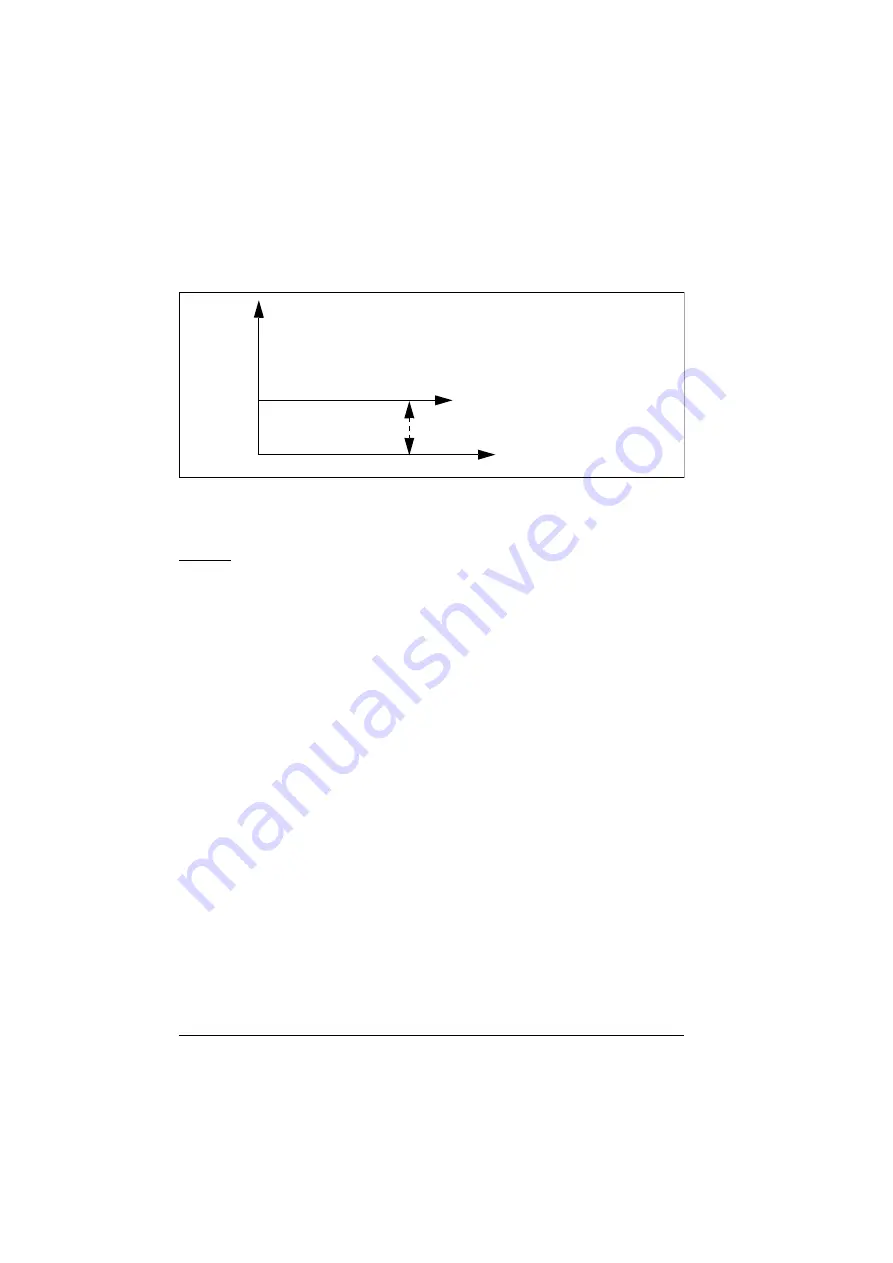
The below graph shows the PID trim output in direct mode throughout the speed
range. A fixed trim speed reference is added throughout the speed range.
Note:
In the above graph, it is assumed that the PID output is limited/stable at 100.
This is for understanding purpose only. In real case scenario, PID output can vary
based on the setpoint and actual.
Example
If,
=
= 1500 rpm
= 100 (limited to 100)
= 0.5
Then,
Proportional
The proportional method is suitable for applications where tension control is required
throughout the speed range but not near to zero speed.
In this mode, the PID trimmed output (
) is relative to
the reference selected by parameter
and with
or
It is recommended that the speed reference selected in
and the reference source selected in
and
are same. This is required to make the proportional mode active.
In most of the use cases, the process speed reference is connected in
. For example, if EXT1 control mode is used and the reference
ct
Drive speed reference
0
Par40.05
100
100
----------
1500 0.5
=
Par40.05
750
=
Summary of Contents for ACS560
Page 1: ...ABB GENERAL PURPOSE DRIVES ACS560 standard control program Firmware manual...
Page 4: ...4...
Page 30: ...30 Start up control with I O and ID run...
Page 32: ...32 Using the control panel...
Page 100: ...100 Program features...
Page 153: ...Control macros 153...
Page 160: ...160...
Page 374: ...374 Parameters...
Page 408: ...408 Additional parameter data...
Page 466: ...466 Fieldbus control through the embedded fieldbus interface EFB...
Page 504: ...504 Control chain diagrams...
Page 508: ...508 Parameterization with drive composer...
Page 512: ...512 Parameterization with automation builder drive manager...


