MAKING MODERN LIVING POSSIBLE
Operating Instructions D-Frame
VLT® HVAC Drive FC 100
Page 1: ...MAKING MODERN LIVING POSSIBLE Operating Instructions D Frame VLT HVAC Drive FC 100...
Page 2: ...r is connected to the AC mains the motor may be started by means of an external switch a serial bus command an input reference signal or a cleared fault condition Use appropriate cautions to guard aga...
Page 3: ...Safety VLT HVAC Drive D Frame Operating Instructions MG16D102 VLT is a registered Danfoss trademark...
Page 4: ...A 11 2 4 2 2 Earthing Grounding IP20 Enclosures 12 2 4 2 3 Earthing Grounding IP21 54 Enclosures 12 2 4 3 Motor Connection 12 2 4 4 Motor Cable 15 2 4 5 Motor Rotation Check 15 2 4 6 AC Mains Input Co...
Page 5: ...29 5 4 International North American Default Parameter Settings 29 5 5 Parameter Menu Structure 30 5 5 1 Main Menu Structure 31 5 6 Remote Programming with MCT 10 Set up Software 35 6 Application Examp...
Page 6: ...ons 58 10 2 General Technical Data 59 10 3 Fuse Tables 64 10 3 1 Protection 64 10 3 2 Non UL Compliance 64 10 3 3 UL Compliance 65 10 3 4 Connection Tightening Torques 65 Index 66 Contents VLT HVAC Dr...
Page 7: ...y 2 04 05 06 2 RS 485 serial bus connector 10 Lifting ring 3 Digital I O and 24 V power supply 11 Mounting slot 4 Analog I O connector 12 Cable clamp PE 5 USB connector 13 Earth ground 6 Serial bus te...
Page 8: ...waveform output The frequency and voltage of the output are regulated to control the motor speed or torque The frequency converter can vary the speed of the motor in response to system feedback such...
Page 9: ...erters kW High Overload 75 90 110 132 160 200 250 315 315 kW Normal Overload 90 110 132 160 200 250 315 355 400 400 V D3h D3h D3h D4h D4h D4h 500 V D3h D3h D3h D4h D4h D4h 525 V D4h D3h D3h D4h D4h D4...
Page 10: ...ad current for peak motor performance Motor size and frequency converter power must match for proper overload protection If frequency converter rating is less than motor full motor output cannot be ac...
Page 11: ...Straps where Indicated WARNING The angle from the top of the frequency converter to the lifting cables should be 60 or greater 2 3 3 Wall Mounting IP21 NEMA 1 and IP54 NEMA 12 Units Consider the follo...
Page 12: ...otor Analog Output Interface relay1 relay2 ON Terminated OFF Open Brake resistor NPN Sink PNP Source 240Vac 2A 400Vac 2A Illustration 2 2 WARNING EQUIPMENT HAZARD Rotating shafts and electrical equipm...
Page 13: ...the quicker the trip response The overload provides Class 20 motor protection See 8 Warnings and Alarms for details on the trip function Because the motor wiring carries high frequency current it is i...
Page 14: ...Use the clamps provided with the equipment for proper earth connections ground connections Do not earth ground one frequency converter to another in a daisy chain fashion Keep the earth ground wire c...
Page 15: ...2 6 Earthing Grounding for IP21 54 Enclosures CAUTION GROUNDING HAZARD Do not use conduit connected to the frequency converter as a replacement for proper grounding Ground currents are higher than 3...
Page 16: ...0 0 0 200 7 9 94 3 7 244 9 6 0 0 0 272 10 7 0 0 0 S U W R T V 3X M8x20 STUD WITH NUT SECTION A A MAINS TERMINALS MAINS TERMINAL SECTION B B MOTOR TERMINALS MOTOR TERMINAL 130BC305 10 Illustration 2 7...
Page 17: ...INAL 130BC332 10 Illustration 2 9 Terminal Locations D2h A A B B 33 1 3 0 0 0 91 3 6 149 5 8 211 8 3 265 10 4 319 12 6 200 7 9 0 0 0 319 12 6 376 14 8 293 11 5 255 10 0 0 0 0 306 12 1 284 11 2 0 0 0 2...
Page 18: ...rical codes for cable sizes Connect 3 phase AC input power wiring to terminals L1 L2 and L3 see Illustration 2 11 130BC254 10 2 1 Illustration 2 11 Connecting to AC Mains 1 Mains connection 2 Motor co...
Page 19: ...centage value Screen type i e braided or twisted pattern a Aluminium clad with copper wire b Twisted copper wire or armoured steel wire cable c Single layer braided copper wire with varying percentage...
Page 20: ...13 18 19 27 29 32 33 20 37 Illustration 2 17 Control Terminal Locations Connector 1 provides four programmable digital input terminals two additional digital terminals programmable as either input or...
Page 21: ...nstalled Each node connected within a given network must have a unique node address across all segments Terminate each segment at both ends using either the termination switch S801 of the frequency co...
Page 22: ...air flow for cooling EMC considerations Check for proper installation regarding electromagnetic compatibility Environmental consider ations See equipment label for the maximum ambient operating temper...
Page 23: ...onal Programming Frequency converters require basic operational programming before running for best performance Basic operational programming requires entering motor nameplate data for the motor being...
Page 24: ...tart It is the responsibility of the user to ensure safe operation under any condition Failure to ensure that the motor system and any attached equipment is ready for start could result in personal in...
Page 25: ...s recommended after application set up by the user is completed CAUTION MOTOR START Ensure that the motor system and any attached equipment is ready for start It is the responsibility of the user to e...
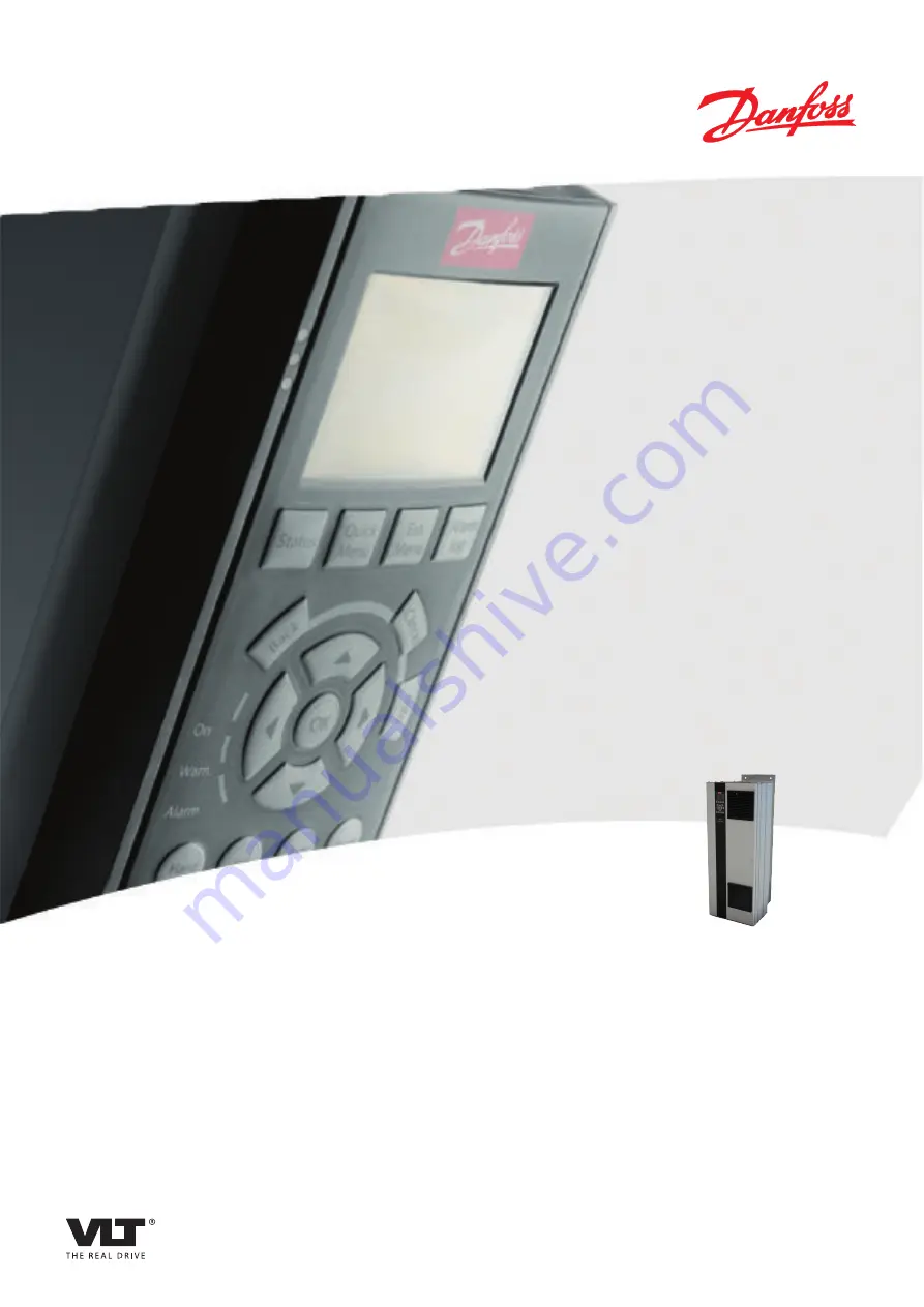
Page 26: ...ogramming Guide MG33MXYY for details on use of the NLCP 4 1 1 LCP Layout The LCP is divided into four functional groups see Illustration 4 1 Auto on Reset Hand on Off Status Quick Menu Main Menu Alarm...
Page 27: ...Status Quick Menu Main Menu Alarm Log Illustration 4 4 Key Function Status Shows operational information In Auto mode press to toggle between status read out displays Press repeatedly to scroll throu...
Page 28: ...nd at the bottom of the LCP 130BP046 10 Hand on Off Auto on Reset Illustration 4 6 Key Function Hand On Starts the frequency converter in local control Use the navigation keys to control frequency con...
Page 29: ...f the frequency converter Initialisation can be through 14 22 Operation Mode or manually Initialisation using 14 22 Operation Mode does not change frequency converter data such as operating hours seri...
Page 30: ...in open loop using the quick menu This procedure programs the frequency converter to receive a 0 10 V DC analog control signal on input terminal 53 The frequency converter will respond by providing 20...
Page 31: ...er that the minimum voltage received on Terminal 53 0 V equals 20 Hz output 130BT773 11 Q3 21 14 7 0 00 A 1 1 Analog Reference 6 14 Terminal 53 Low Ref Feedb Value 000020 000 Illustration 5 8 10 6 15...
Page 32: ...minal 18 Digital Input 8 Start 14 7 0 00A 1 1 Digital Inputs Illustration 5 13 5 4 International North American Default Parameter Settings Setting 0 03 Regional Settings 0 International or 1 North Ame...
Page 33: ...requency converter with system details it needs to operate properly System details may include such things as input and output signal types programming terminals minimum and maximum signal ranges cust...
Page 34: ...r Ramps 3 80 Jog Ramp Time 3 81 Quick Stop Ramp Time 3 82 Starting Ramp Up Time 3 9 Digital Pot Meter 3 90 Step Size 3 91 Ramp Time 3 92 Power Restore 3 93 Maximum Limit 3 94 Minimum Limit 3 95 Ramp D...
Page 35: ...tance 12 21 Process Data Config Write 12 22 Process Data Config Read 12 27 Primary Master 12 28 Store Data Values 12 29 Store Always 12 3 EtherNet IP 12 30 Warning Parameter 12 31 Net Reference 12 32...
Page 36: ...ID Start Speed Hz 20 84 On Reference Bandwidth 20 9 PID Controller 20 91 PID Anti Windup 20 93 PID Proportional Gain 20 94 PID Integral Time 20 95 PID Differentiation Time 20 96 PID Diff Gain Limit 21...
Page 37: ...Feedb Value 26 25 Term X42 3 High Ref Feedb Value 26 26 Term X42 3 Filter Time Constant 26 27 Term X42 3 Live Zero 26 3 Analog Input X42 5 26 30 Terminal X42 5 Low Voltage 26 31 Terminal X42 5 High Vo...
Page 38: ...oaded to the frequency converter Or the entire frequency converter profile can be loaded onto the PC for back up storage or analysis The USB connector or RS 485 terminal are available for connecting t...
Page 39: ...nput 2 Coast inverse Default Value Notes comments Parameter group 1 2 must be set according to motor Table 6 1 AMA with T27 Connected Parameters FC 24 V 24 V D IN D IN D IN COM D IN D IN D IN D IN 10...
Page 40: ...9 Terminal 37 Safe Stop 1 Safe Stop Alarm Default Value Notes comments If 5 12 Terminal 27 Digital Input is set to 0 No operation a jumper wire to terminal 27 is not needed Table 6 5 Start Stop Comman...
Page 41: ...Notes comments Table 6 8 External Alarm Reset Parameters FC 24 V 24 V D IN D IN D IN COM D IN D IN D IN D IN 10 V A IN A IN COM A OUT COM 12 13 18 19 20 27 29 32 33 37 50 53 54 55 42 39 A53 U I 5k 13...
Page 42: ...RS 485 Network Connection CAUTION Thermistors must use reinforced or double insulation to meet PELV insulation requirements Parameters FC 24 V 24 V D IN D IN D IN COM D IN D IN D IN D IN 10 V A IN A...
Page 43: ...rnal equipment may then indicate that service may be required If the feedback error goes below the limit again within 5 s then the frequency converter continues and the warning disappears But Relay 1...
Page 44: ...nals and or the serial communi cation Hand on The frequency converter can be controlled by the navigation keys on the LCP Stop commands reset reversing DC brake and other signals applied to the contro...
Page 45: ...ed down Operation status Jog request A jog command has been given but the motor will be stopped until a run permissive signal is received via a digital input Jogging The motor is running as programmed...
Page 46: ...d the motor will start after the start delay time expires Start fwd rev Start forward and start reverse were selected as functions for two different digital inputs parameter group 5 1 The motor will s...
Page 47: ...frequency converter logic will continue to operate and monitor the frequency converter status After the fault condition is remedied the frequency converter can be reset It will then be ready to start...
Page 48: ...ts Auto on Reset Hand on Off B a c k C a n c e l Info OK On Alarm Warn 130BB467 10 Illustration 8 3 Warn LED Alarm LED Warning ON OFF Alarm OFF ON Flashing Trip Lock ON ON Flashing Table 8 1 Warnings...
Page 49: ...istor short circuited X 26 Brake resistor power limit X X 2 13 Brake Power Monitoring 27 Brake chopper short circuited X X 28 Brake check X X 2 15 Brake Check 29 Drive over temperature X X X 30 Motor...
Page 50: ...73 Safe Stop Auto Restart 76 Power Unit Setup X 77 Reduced Power Mode 79 Illegal PS config X X 80 Drive Initialized to Default Value X 91 Analog input 54 wrong settings X 92 NoFlow X X 22 2 93 Dry Pum...
Page 51: ...e intermediate circuit voltage DC is lower than the low voltage warning limit The limit is dependent on the frequency converter voltage rating The unit is still active WARNING ALARM 7 DC overvoltage I...
Page 52: ...imit is exceeded during ramp up extend the ramp up time If the generator torque limit is exceeded during ramp down extend the ramp down time If torque limit occurs while running possibly increase the...
Page 53: ...n 90 of the brake resistance power If 2 Trip is selected in 2 13 Brake Power Monitoring the frequency converter will trip when the dissipated braking power reaches 100 WARNING There is a risk of subst...
Page 54: ...ocessor software version 1299 Option SW in slot A is too old No Text 1300 Option SW in slot B is too old 1301 Option SW in slot C0 is too old 1302 Option SW in slot C1 is too old 1315 Option SW in slo...
Page 55: ...thin the specified range in 4 11 Motor Speed Low Limit RPM and 4 13 Motor Speed High Limit RPM the frequency converter shows a warning When the speed is below the specified limit in 1 86 Trip Speed Lo...
Page 56: ...eration can be resumed when the applies 24 V DC to T 37 again when the motor temperature reaches an acceptable level and when the Digital Input from the is deactivated When that happens a reset signal...
Page 57: ...verter for normal operation WARNING 251 New typecode The power card or other components have been replaced and the typecode changed Reset to remove the warning and resume normal operation Warnings and...
Page 58: ...Check the wiring for shorts or incorrect connections If the display continues to cut out follow the procedure for display dark Motor not running Service switch open or missing motor connection Check...
Page 59: ...amp time settings Check parameter group 2 0 DC brake and 3 0 Reference limits Open power fuses or circuit breaker trip Phase to phase short Motor or panel has a short phase to phase Check motor and pa...
Page 60: ...parameters in parameter group 4 6 Check if noise and or vibration have been reduced to an acceptable limit Turn off over modulation in 14 03 Overmodulation Change switching pattern and frequency in p...
Page 61: ...180 218 274 333 407 Continuous kVA at 460 V kVA 151 191 241 288 353 426 Max Input current Continuous at 400 V A 204 251 304 381 381 463 463 567 Continuous at 460 500 V A 183 231 291 348 348 427 427 51...
Page 62: ...supply voltage True Power Factor 0 9 nominal at rated load Displacement Power Factor cos near unity 0 98 Switching on input supply L1 L2 L3 power ups maximum one time 2 minutes Environment according t...
Page 63: ...oltage PELV and other high voltage terminals Mains Functional isolation PELV isolation Motor DC Bus High voltage Control 24V RS485 18 37 130BA117 10 Illustration 10 1 Pulse inputs Programmable pulse i...
Page 64: ...ad DC 1 1 on 1 2 NO Resistive load 80 V DC 2 A Max terminal load DC 13 1 on 1 2 NO Inductive load 24 V DC 0 1 A Max terminal load AC 1 1 on 1 3 NC Resistive load 240 V AC 2 A Max terminal load AC 15 1...
Page 65: ...rformance 10 C Temperature during storage transport 25 65 70 C Maximum altitude above sea level without derating 1000 m Maximum altitude above sea level with derating 3000 m Derating for high altitude...
Page 66: ...If a mains phase is missing the frequency converter trips or issues a warning depending on the load Monitoring of the intermediate circuit voltage ensures that the frequency converter trips if the int...
Page 67: ...Provide overload protection to avoid fire hazard due to overheating of the cables in the installation The frequency converter is equipped with an internal over current protection that can be used for...
Page 68: ...0URD31KI0550 N250 170M4016 LA50QS600 4 L50S 600 FWH 600A 20 610 31 630 A50QS600 4 6 9URD31D08A0630 A070URD31KI0630 N315 170M4017 LA50QS800 4 L50S 800 FWH 800A 20 610 31 800 A50QS800 4 6 9URD32D08A0800...
Page 69: ...gnal 27 28 41 System 5 Terminals 21 25 41 43 29 17 Wiring 9 10 11 19 Cooling Cooling 7 Clearance 19 Copying Parameter Settings 25 Current Limit 21 Rating 7 48 D DC Current 5 42 Link 48 Derating 62 63...
Page 70: ...eeds 20 Status 5 Wiring 9 10 19 Mounting 19 Multiple Frequency Converters 10 12 N Navigation Keys 20 27 41 23 25 Noise Isolation 9 19 O Open Loop 27 62 Operation Keys 25 Optional Equipment 20 5 Output...
Page 71: ...2 Supply Voltage 15 17 51 60 Surroundings 62 Switching Frequency 42 System Feedback 5 T Temperature Limits 19 Terminal 53 27 28 Programming 18 Programming Examples 29 Thermistor Thermistor 15 49 39 Co...
Page 72: ...www danfoss com drives MG16D102 130R0290 MG16D102 Rev 2012 04 24...
Page 73: ......