A H 5 0 0 M o t i o n C o n t r o l M o d u l e M a n u a l
Set P0-02 to 16#120. If the servo drive is connected successfully, the value shown on the
display of the servo drive will be 16#80. If the value shown on the display is 16#06, users
have to check whether there is a servo drive whose station address is 16#01.
Writing a program
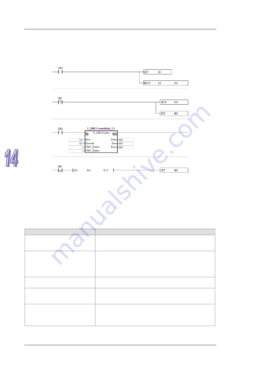
Write T_DMCControllnit in a program for AH20MC-5A.
In this example, after the PLC used begins to operate, the servo drive whose station address is
1 will be initialized first. After the initialization of the servo drive whose station address is 1 is
complete, the value shown on the display of the servo drive will be 16#111, the servo drive will
be operable, and the servo drive will be ON.
* When the motion control function block T_DMCControllnit is used, only one servo drive can be
initialized at a time.
14.8
Troubleshooting
Problem
Remedy
The DMCNET connection LED
indicator on an AH500 series
motion control module is not ON.
Check whether a networking cable is connected to the
AH500 series motion control module correctly, and check
whether a terminal resistor is connected correctly.
The value of bit 0~bit 3 in SR1073
(SR1173, SR1273…) is 0.
Users have to instruct the servo drive used to reset NMT by
means of bit 0~bit 3 in SR1072 (SR1172, SR1272…). If the
servo drive is still not connected, the users have to check
whether the cables connected to the hardware used are
loose, and check whether a terminal resistor is connected.
The value of a parameter in a
servo drive is incorrect.
Check whether the parameter can be set when the servo is
ON/OFF, and check whether the data type set is correct.
After a value is written into a servo
drive, no response is received in a
specified amount of time.
Check whether the servo drive can be connected correctly.
After P0-02 in a servo drive is set
to 16#120, the value shown on the
display of the servo drive is 16#06.
1. Check whether there is a servo drive whose node ID is
1 on the DMCNET created.
2. Check whether the cables connected to the hardware
used are loose.
1 4 - 1 8
Содержание AH500
Страница 9: ...viii...
Страница 52: ...Chapter 2 Hardware Specifications and Wiring Wiring AH10PM 5A and a Panasonic CN5 series servo drive 2 31...
Страница 53: ...AH500 Motion Control Module Manual Wiring AH10PM 5A and a Yaskawa servo drive 2 32...
Страница 54: ...Chapter 2 Hardware Specifications and Wiring Wiring AH10PM 5A and a Mitsubishi MJR2 series servo drive 2 33...
Страница 55: ...AH500 Motion Control Module Manual Wiring AH10PM 5A and a Fuji servo drive 2 34...
Страница 115: ...AH500 Motion Control Module Manual 4 16 MEMO...
Страница 375: ...AH500 Motion Control Module Manual 5 260 MEMO...
Страница 376: ...Chapter 6 Data Transmission Table of Contents 6 1 Functions 6 2 6 2 Parameters 6 2 6 3 Usage 6 5 6 1...
Страница 383: ...AH500 Motion Control Module Manual 6 8 MEMO...
Страница 419: ...AH500 Motion Control Module Manual 7 36 MEMO...
Страница 436: ...Chapter 8 Electronic Cam 8 17...
Страница 482: ...Chapter 10 High speed Counters and High speed Timers 3 The cyclic mode is used to measure a frequency 10 7...
Страница 483: ...AH500 Motion Control Module Manual 10 8 MEMO...
Страница 505: ...AH500 Motion Control Module Manual 12 8 MEMO...
Страница 515: ...AH500 Motion Control Module Manual 13 10 MEMO...
Страница 544: ...Appendix A Error Code Table Table of Contents A 1 Error Code Table A 2 A 1...
Страница 547: ...AH500 Motion Control Module Manual A 4 MEMO...


