9. COMMUNICATION DATA DESCRIPTION
IMS01T28-E4
9-39
9.3 Engineering Setting Data Items
Setting procedure of Engineering setting data items
When RUN/STOP switching (RKC communication identifier: RS, Modbus register address: 006DH) is set
to “0: STOP (control stop),” Engineering setting data can be configured.
During RUN (control), the attribute of the Engineering setting data is RO (read only).
9.3.1 Precaution against parameter change
If the following parameters are changed, related settings will also change.
Before changing a parameter, be sure to make a record of all the settings (Normal setting
data and Engineering setting data).
After changing a parameter, be sure to check all the settings (Normal setting data and
Engineering setting data).
When the Input type parameter is changed
When the input type is changed, all the setting in the following table will be changed. Reset the settings to
the values that you wish to use.
Input type
(RKC communication identifier: XI, Modbus address: 0176H to 0177H)
Items that are initialized:
Data type
Items
Default value
Engineering
setting data
Decimal point position
RTD input:
2 or 3
Voltage (V) input: 3
Input scale high
RTD input:
Maximum value of the selected input range
Voltage (V) input: 100.00
Input scale low
RTD input:
Minimum value of the selected input range
Voltage (V) input: 0.00
Input error determination point (high)
RTD input:
Input range high
(5 % of Input span)
Voltage (V) input: +105.00
Input error determination point (low)
RTD input:
Input range low
(5 % of Input span)
Voltage (V) input:
5.00
Burnout direction
0: Upscale
Continued on the next page.
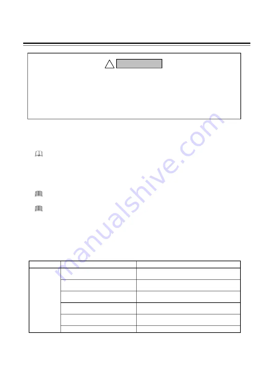
The Engineering setting data should be set according to the application before
setting any parameter related to operation. Once the Engineering setting data are
set correctly, those data are not necessary to be changed for the same
application under normal conditions. If they are changed unnecessarily, it may
result in malfunction or failure of the instrument. RKC will not bear any
responsibility for malfunction or failure as a result of improper changes in the
Engineering setting.
WARNING
!
Summary of Contents for Z-TIO-G
Page 8: ...i 6 IMS01T28 E4 MEMO...
Page 16: ...IMS01T28 E4 1 8 MEMO...
Page 22: ...2 6 IMS01T28 E4 MEMO...
Page 34: ...4 MOUNTING 4 4 IMS01T28 E4 4 2 Dimensions Terminal type module 85 100 5 Unit mm 30 6 7...
Page 52: ...5 14 IMS01T28 E4 MEMO...
Page 82: ...7 18 IMS01T28 E4 MEMO...
Page 211: ...TROUBLE SHOOTING IMS01T28 E4 10 1 10 1 Solutions for Problems 10 2...
Page 216: ...10 6 IMS01T28 E4 MEMO...
Page 217: ...SPECIFICATIONS IMS01T28 E4 11 1...
Page 230: ...11 14 IMS01T28 E4 MEMO...
Page 244: ...A 4 IMS01T28 E4 MEMO...
Page 245: ...The first edition SEP 2012 IMQ00 The fourth edition FEB 2019 IMQ00...


