Initial Operation and User Interface
45/121
Operating Manual dryve D1, ST-, DC-, EC/BLDC-Motor Control System - V2.4
5.5 Axis Configuration
Available settings for linear or rotational axis configuration are described in the following.
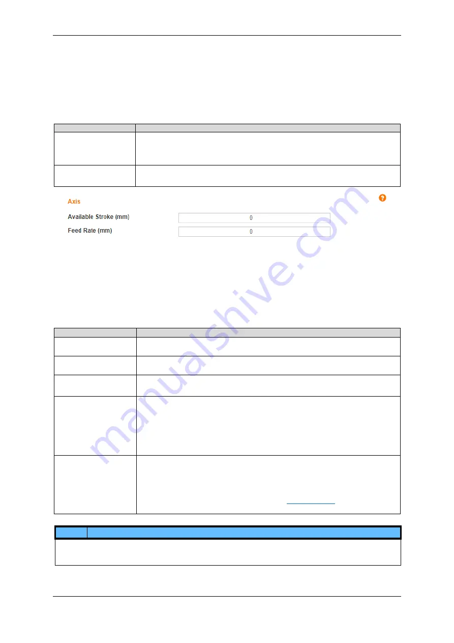
5.5.1 Axis
Necessary basic settings for exact positioning.
Settings
Description
Available Stroke
Specifying the movement window for "ABS" mode (Absolute Positioning). All other modes
remain unaffected by this restriction. This window starts at the zero-point set after a homing
run and ends at the entered value. Only movements within this window are permitted in the
"Absolute Positioning" mode. Specification of a negative window is not possible
.
Feed Rate
The feed rate indicates the resulting traversing movement per drive shaft rotation
If a rotational axis is used, the value 360° must be entered for the feed rate.
1.
Enter the desired maximum distance
2.
Enter the "Feed rate"
5.5.2 Motion Limits
It is recommended to set movement limits. They ensure a safe and reliable operation and avoid damage and malfunctions due
to incorrect entries.
Setting
Description
Max. Velocity
Maximum motor, carriage or rotation arm velocity. Used to avoid errors due to accidental
entries of excessively high values in the Drive Profile.
Jog Velocity
Velocity of the linear axis, the rotation axis or the motor in Tipp/Teach mode and the position
adaption function.
The entered velocity must be lower than the “Max. Velocity”
Max. Acceleration
Maximum motor, carriage or rotation arm acceleration.
Used as the acceleration with the Tipp/Teach mode and the position adaption function.
S-Curve
Selection between speed optimized trapezoidal or jerk reduce sinusoidal acceleration and
deceleration ramps.
Trapezoidal ramps are usually used with 1 axis applications without special requirements
regarding a jerk forming at transitions between acceleration or deceleration phases to a
constant velocity phase.
Sinusoidal ramps are used if jerk sensitive goods are transported or several axes must interact
(e.g. Delta Robot)
Quick-stop
Deceleration rate when a movement is stopped in an emergency.
To stop a movement in time to avoid an accident, it is recommended that the "Quick Stop"
deceleration rate is set higher than the
“Max. Acceleration” (recommendation: factor 10). It is
important to ensure, that the increased deceleration rate is appropriate for the intended
application and cannot destroy the mechanical structure.
A
“Quick-Stop” is executed if the “Quick-Stop” button (
7) is used, the
“Enable” signal at DI 7 is revoked.
NOTE
The maximal acceleration of a movement using S-Curve will be reached in the infliction point as the set acceleration is used
as the average across the acceleration phase. It can reach values as double as high as the set acceleration value on the
“Drive Profile” page.


