Installation
22/121
Operating Manual dryve D1, ST-, DC-, EC/BLDC-Motor Control System - V2.4
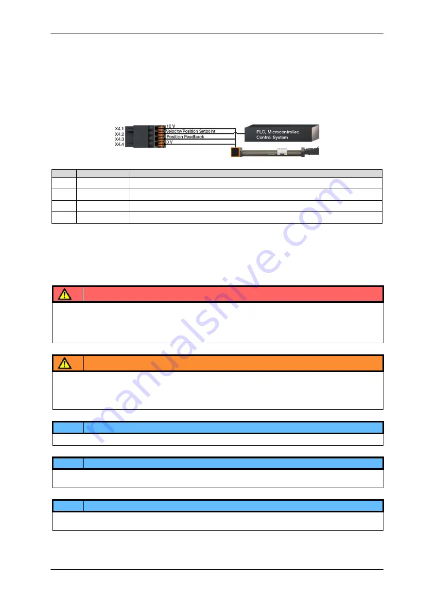
X4 Analogue Inputs Connector
With the Analogue Inputs it is possible to process position and velocity setpoints as well as position feedbacks with a 0 V to 10
V or ± 10 V signal. An analogue position setpoint potential can be supplied by an external master (i.e. a higher-level control
system, whereby the external voltage supply must be connected to the X4.4 ground contact) to X4.2 as well as voltage-
changing components (e.g. potentiometer, temperature-dependent resistors, etc.).
For analogue position feedback, an axis mounted absolute value feedback (e.g. a precision multiturn potentiometer) can be
connected to X4.3.
The dryve D1 has got an build in 10 V voltage supply. It can be used to directly supply connectable components for the
stipulation of position setpoints and for feedback as well.
Pin
Assignment
Designation
X4.1
10 V
Voltage Supply Output
X4.2
AI 1
Velocity or Position Setpoint Input
X4.3
AI 2
Position Feedback input
X4.4
0 V
Voltage Supply Output
X5 Motor/Brake/Brake Resistor Connector
The dryve D1 can control either a Stepper Motor, a DC Motor or an EC Motor. The following wiring diagrams demonstrate the
connection for a Stepper Motor (X5.1 to X5.4), DC-Motor (X5.1 to X5.2) and EC/BLDC-Motor (X5.1 to X5.3).
In case an EC/BLDC motor is being used an additional Brake Resistor might be attached to X5.4 and X5.5 to dissipate the
generated excessive energy.
WARNING!
-
Danger of malfunction
-
Fire hazard
Use the dryve D1 motor control system only to control Stepper, DC or EC Motors that are compatible with technical
connectivity and technical performance of the dryve D1 motor control system.
NOTE
Only one motor at a time is to be connected!
NOTE
The connector X5.5 is directly connected to the shared ground of the Logic and Load Supply at X1.2 and is not intended for
the connection of external earthing wires.
NOTE
If the case of uncertainties or connection of a Stepper Motor with 6 or 8 connecting wires, please consult the motor data
sheet and connect the wires according to the instructions.
DANGER!
-
Danger of falling load
The motor holding brake is not suitable for slowing down the load on a vertical axis.
Never work under unsecured vertical axes and loads.
Secure the axis or load against falling by a mechanical safety device or other approved safety method.


