Agilent Technologies J-BERT N4903B User Manual Download Page 447

N O T E

The Jitter Tolerance Compliance measurement is a software option that requires a
license. For details on how to obtain and install such licenses refer to 

“Obtaining a

License” on page 535

.

Measurement Principle

The Optical Internetworking Forum (OIF) and other institutions have proposed and

published standards for testing the performance of data receivers and receiver

circuits in the presence of jitter.
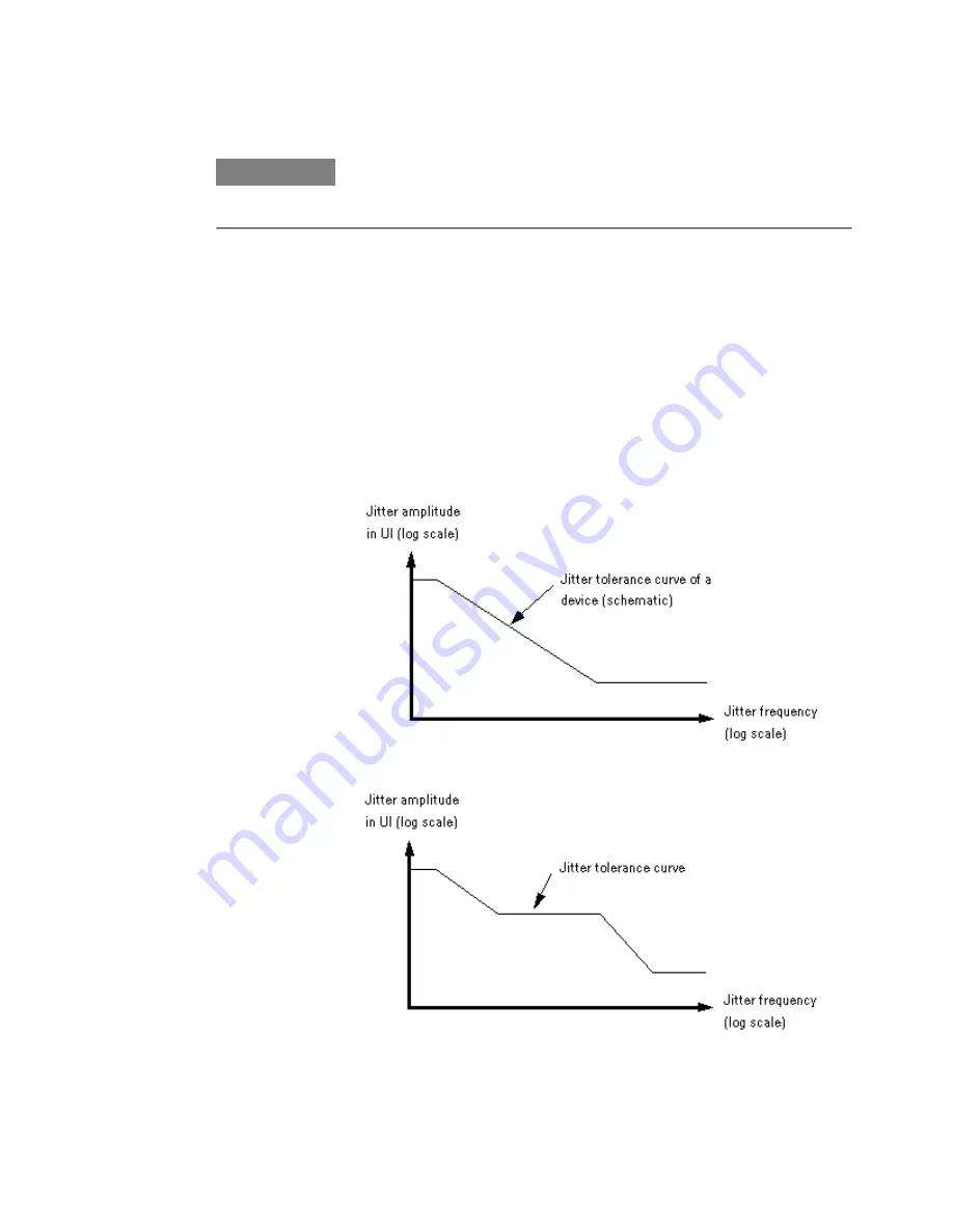
These standards prescribe the required jitter tolerance over jitter frequency. The

jitter tolerance for each frequency point is defined by a jitter amplitude (normalized

to the bit rate and hence specified in Unit Intervals – UI) and a BER threshold which

must not be exceeded.

A simple example is shown in the figure below:

Some standards are more detailed, as illustrated in the following figure:

Jitter Tolerance Tests

8

Agilent J-BERT N4903B High-Performance Serial BERT

447

Jitter Tolerance Curves

Summary of Contents for J-BERT N4903B

Page 1: ...S Agilent J BERT N4903B High Performance Serial BERT User Guide s Agilent Technologies ...

Page 2: ...ware and or software described in this document are furnished under a license and may be used or copied only in accordance with the terms of such license Restricted Rights Legend If software is for use in the performance of a U S Government prime contract or subcontract Software is delivered and licensed as Commercial computer software as defined in DFAR 252 227 7014 June 1995 or as a commercial i...

Page 3: ...trument s Concepts 37 Setting up External Instrument s Procedure 42 Setting up External Instrument s Reference 51 3 Setting up Patterns Setting up Patterns Concepts 61 User Patterns 65 User Patterns Concepts 65 User Patterns Procedures 71 User Patterns Reference 76 Software Generated PRBS 91 Software Generated PRBS Concepts 91 Software Generated PRBS Procedures 93 Software Generated PRBS Reference...

Page 4: ...te Procedures 141 Bit Rate Reference 143 Trigger Ref Clock Output 145 Trigger Ref Clock Output Concepts 145 Trigger Ref Clock Output Procedures 145 Trigger Ref Clock Output Reference 146 Aux Data Out 149 Aux Data Output Concepts 149 Aux Data Out Procedures 149 Aux Data Output Reference 154 Delay Control Input 155 Delay Control Input Concepts 155 Delay Control Input Procedures 156 Delay Control Inp...

Page 5: ...ing Point Setup Reference 198 Trigger and Aux Output 203 Trigger and Aux Output Concepts 203 Trigger and Aux Output Procedures 203 Trigger and Aux Output Reference 204 Pattern Synchronization 205 Pattern Synchronization Concepts 205 Pattern Synchronization Procedures 216 Pattern Synchronization Reference 218 Error Accumulation 220 Error Accumulation Concepts 220 Error Accumulation Procedures 220 E...

Page 6: ... 302 Error Location Capture Concepts 302 Error Location Capture Procedures 304 Error Location Capture Reference 305 Fast Eye Mask 307 Fast Eye Mask Concepts 307 Fast Eye Mask Procedures 309 Fast Eye Mask Reference 311 Eye Diagram 315 Eye Diagram Concepts 315 Eye Diagram Procedures 320 Eye Diagram Reference 332 Spectral Jitter 342 Spectral Jitter Concepts 342 Spectral Jitter Procedures 351 Spectral...

Page 7: ...ocedures 431 Interference Channel Setup Reference 432 Jitter Tolerance Characterization 433 Jitter Tolerance Characterization Concepts 433 Jitter Tolerance Characterization Procedures 438 Jitter Tolerance Characterization Reference 443 Jitter Tolerance Compliance 446 Jitter Tolerance Compliance Concepts 446 Jitter Tolerance Compliance Procedures 454 Jitter Tolerance Compliance Reference 462 9 Solv...

Page 8: ...figuring the Instrument Concepts 528 Configuring the Instrument Procedures 529 Configuring the Instrument Reference 531 Configuring the Touchscreen 531 Configuring the Touchscreen Procedures 531 Configuring the Touchscreen Reference 533 Installing Software Licenses 535 Installing Software Licenses Procedures 535 Installing Software Licenses Reference 535 Installing Hardware Options 536 Installing ...

Page 9: ...ent Procedures 558 Preset Instrument State 562 Preset Instrument State Procedures 562 Self Test 563 Self Test Concepts 563 Self Test Procedures 563 Self Test Reference 564 Index 567 Agilent J BERT N4903B High Performance Serial BERT 9 ...

Page 10: ...10 Agilent J BERT N4903B High Performance Serial BERT ...

Page 11: ...ypes of testing you can do with the Serial BERT Connecting the DUT Concepts on page 29 tells you how you should connect your DUT to the Serial BERT Introduction to the Serial BERT Introduction to the Serial BERT Concepts These topics explain some of the basics of BER Serial BERT and BER testing with the Serial BERT Important Information about the Pattern Generator Outputs The pattern generator out...

Page 12: ...ous malfunction in the operating system the Agilent Recovery System can be used to repair the system See Agilent Recovery System Procedures on page 525 Understanding BER Bit error ratio BER is the most fundamental measure of system performance It is the ratio of the number of errored bits to the total number of bits received For example 1 error in 1000 bits corresponds to a BER of 1 1000 or 1x10 3...

Page 13: ...of 10 bits that corresponds to a SER of 1 1000 or 1x10 3 This would be displayed on the instrument as 1E 3 Refer to the following table to familiarize yourself with how SERs are displayed Notice that smaller exponents correspond to higher SERs and larger exponents correspond to lower SERs Table 2 Fraction Exponent Instrument Display 1 1 1 x 100 1E 0 1 10 1 x 10 1 1E 1 1 100 1 x 10 2 1E 2 1 1000 1 ...

Page 14: ... the IVI COM interface Remote commands similar to HP Agilent 71603B A variety of ways in which to accumulate and view test results A collection of example patterns Convenient online documentation Automatic setup of optimum sampling point A variety of powerful advanced analysis tools Special support for jitter analysis and characterization Which Features are Available The Serial BERT is available w...

Page 15: ...patterns filtering of up to 4 user definable filler symbols filtering without any dead times up to 11 5 Gb s data rates 12 5 Gb s when using analyzer with external clock display of the error ratio as SER or calculated BER For PCIe3 PCI Express 3 0 the option A02 enables the error counter to ignore changes in the length of 128 130 bit coded SKPOS Skip Ordered Sets To use this functionality N4903B s...

Page 16: ...ia J BERT N4903B or stand alone USB and LAN connectivity N4916B De Emphasis Signal Converter The N4916B is a 4 tap de emphasis signal converter with optional clock multiplier It is intended to accurately characterize your multi gigabit serial interfaces Following are the features and benifits of N4916B Generates 4 tap de emphasis with variable de emphasis levels Supports data rates from 660 Mb s t...

Page 17: ...cated closely to DUT Controlled via the local user interface of Serial BERT Remote Programming is transparently done via Serial BERT M8061A 28 Gb s Multiplexer with De emphasis The Agilent s M8061A is a 2 1 multiplexer to characterize serial interfaces of up to 28 4 Gb s with optional de emphasis to extend the rate of J BERT N4903B pattern generator Data rates up to 28 4 Gb s are used for Optical ...

Page 18: ...ical idle The Agilent M8061A is available with the following two options Option M8061A 004 provides 4 tab de emphasis feature Option M8061A 008 provides extension to 8 tab de emphasis feature These features are only operational when the respective options are installed during manufacturing Navigating the Serial BERT GUI Navigating the Serial BERT GUI Concepts The Serial BERT GUI provides a central...

Page 19: ...he calculated BER Elapsed Time Indicator Displays the progress of the current accumulation period If a measurement is running it displays the measurement progress Show Error Message Button Displays error messages The Show Error Message button uses the following color codes to indicate different states No error messages The button will be in disabled state New unread errors The triangle icon on the...

Page 20: ... ON or Jitter ISI SSC Indicated by green LED Error indicators like Error Sync Loss Data Loss Clock Loss Indicated by red LED N O T E Two additional error indicators Symb Lock and 8b10b Error will appear if you select the error ratio as 8B 10B Symbol Comparison from the Error Detector Error Ratio s window For more details see Symbol Lock Indicator on page 192 and 8b10b Error Indicator on page 192 W...

Page 21: ... Each menu entry on the Menu button has a separator and an arrow sign on it While the separator indicates that the menu item can be directly opened by clicking on the group menu item the arrow sign indicates a horizontally expanding submenu associated to it The following figure explains the usage of the navigation menu Each group menu items has an image assigned to it The image displayed on the me...

Page 22: ...trol the external instruments that are connected to Serial BERT The Pattern menu allows you to Select a pattern Edit a pattern Launch the Sequence Editor The PG Setup menu allows you to launch the following controls Bit Rate Setup Data Output Clock Trigger Output Trigger Ref Clock Setup Aux Data Setup Error Add Setup Alt Pattern and Aux In Setup For more information on PG Setup refer to the sectio...

Page 23: ...tter Eye Opening In addition the Analysis menu also allows you to perform following operations Save Measurement Load Measurement Export Data For more information on Analysis refer to the section Advanced Analysis Concepts on page 227 The Jitter menu allows you to launch the following controls Jitter Setup Interference Channel Jitter Tolerance Characterization Jitter Tolerance Compliance Generate H...

Page 24: ...the section Customizing the Instrument Concepts on page 525 The Help menu launches the online help which provides information on a particular GUI item You have the following possibilities for opening this Help from the Serial BERT user interface Context sensitive Help for all elements of the GUI To get quick information on the meaning of a particular GUI item select What s This from the Help menu ...

Page 25: ...ine what caused the bit errors The analyzer can be set up to work with your device in many different ways To determine the best measurement setup you must first decide how you want to test your device Before actually setting up and making measurements you may want to consider the following questions What is the purpose of your test What are the testing requirements of your device What is the Purpo...

Page 26: ...utput See Why the Serial BERT Repeats Memory Based Patterns on page 69 Do you need more than two patterns or a mix of custom patterns and PRBS Does your device change the input pattern it receives If your device inverts logic then select Data Inverted in the Sampling Point Setup window If your device changes patterns in other ways then you must know the expected output pattern and select it as the...

Page 27: ... are measured and displayed See What Type of Synchronization Should You Use on page 208 Test Times and Confidence Levels A true BER measurement must be statistically valid Because it is not possible to predict with certainty when errors will occur your device must be tested long enough to have confidence in its BER performance The table below lists the test times required for different BERs at spe...

Page 28: ...nd the desired confidence level you can calculate the number of bits that must be measured without error The number of bits in turn can be translated into a period of time at a certain bit rate That is what is done in the above table The following example shows how to calculate the number of bits if the desired BER b is 1E 10 and the desired confidence level C is 95 1 Change formula C 1 e nb to so...

Page 29: ... This is indicated in the PG Setup Data Output or PG Setup Clock Trigger Output screen 2 Connect the DUT as necessary 3 Terminate any non connected Data Out Aux Data Out Clock Out and Trigger Ref Clock Out ports normal and complementary 4 If the outputs are disabled press the 0V Disable button to enable them To avoid damaging your device set up the devices properly before making connections C A U ...

Page 30: ... received by the device is not equal to the data rate sent from the device Diagram 2 Connections for Differential Inputs Application is the same as in Diagram 1 Illustrates how to connect to a device requiring differential signals 1 Planning the Test 30 Agilent J BERT N4903B High Performance Serial BERT ...

Page 31: ...Diagram 3 Connections for an Amplifier Often used for amplifiers Diagram 4 Connections for a Flip Flop Often used for flip flops Planning the Test 1 Agilent J BERT N4903B High Performance Serial BERT 31 ...

Page 32: ... data signals between the MUX DEMUX pair must be set properly Diagram 6 Connections for a DCA or Oscilloscope PGonly Used for measuring the output waveform of your device For the least amount of jitter the clock output signal may be used as a trigger for the oscilloscope 1 Planning the Test 32 Agilent J BERT N4903B High Performance Serial BERT ...

Page 33: ...ce Illustrates the use of an oscilloscope in addition to the error detector N O T E As in all setups the pattern sent to the error detector must be the same as the internal reference pattern of the error detector Dynamic patterns and or patterns with live payloads cannot be used N O T E Diagrams 1 through 8 can use an external clock reference connected to the Clock In port of the pattern generator...

Page 34: ...s Multiplexer The Data In Aux Data In and Aux Clk In of N4876A has to be connected to Data Out Aux Data Out and Aux Clk Out ports of the Serial BERT s respectively The connections should be made using the matched cable kit with the part number N4915A 011 The Data Output has to be connected to the device under test The unused output of the Pattern Generator has to be terminated with 50 Ohm The N487...

Page 35: ...sed in combination with J BERT N4903B as shown below The M8061A is a 2 slot AXIe module that can be controlled via USB from J BERT s user interface For using the CMI and DMI inputs of M8061A you can connect any sinusoidal source with a voltage swing of 0 to 400 mV single ended You can for instance use the sinusoidal sources of N4903B option J20 Use a single ended connection from any of the P1 or P...

Page 36: ...1 Planning the Test 36 Agilent J BERT N4903B High Performance Serial BERT ...

Page 37: ...nal Converter on page 16 3 N4876A 28 Gb s Multiplexer 2 1 For more details refer to the section N4876A 28 Gb s Multiplexer 2 1 on page 17 4 M8061A 28 Gb s Multiplexer with De emphasis For more details refer to the section M8061A 28 Gb s Multiplexer with De emphasis on page 17 Understanding the N4916A B De Emphasis Signal Converter The De Emphasis Signal Converter can be connected between the Data ...

Page 38: ...ter connected between the Data Out port of the pattern generator and the DUT De emphasized signals are used to adapt the signal waveform to the characteristics of real transmission lines as found on printed circuit boards They can considerably reduce the impact of Intersymbol Interference ISI and hence allow longer signal paths De emphasized signals are prescribed by a couple of popular standards ...

Page 39: ...able amplifier to produce the desired output voltage Vpp The other one has an adjustable delay automatically set to one signal clock period and a programmable inverting attenuator amplifier to produce the delayed signal with a lower voltage swing Finally the signals of both branches are added This means the delayed signal voltage is subtracted from the specified peak to peak amplitude It is also p...

Page 40: ...ersa C A U T I O N Be very careful if you set the de emphasis ratio to amplification In this case there is no indication of the peak to peak voltage applied to the DUT You need to calculate or measure the output signal voltage precisely Otherwise you might damage your device The following example illustrates the output of the differential signal with variable de emphasis on pre cursor and 2 post c...

Page 41: ...up to 28 4 Gb s The Data In of N4876A has to be connected to Data Out of the PG Aux Data In to Aux Data Out of PG and Aux Clk In to Aux Clk Out of PG using the using the matched cable kit with the part number N4915A 011 Its Data Output has to be connected to the device under test Understanding the M8061A 28 Gb s Multiplexer with De emphasis The Agilent Technologies M8061A is a 2 1 multiplexer to c...

Page 42: ... This section describes how to use the External Instrument s menu to enable external instruments connected to the J BERT N4903B N O T E Before continuing to next step make sure that the physical connection among the Serial BERT and the external instruments are properly done and then turn them on Also ensure that you have properly installed the external instruments For a complete list of external i...

Page 43: ...ts are properly connected and installed For more information on Config window refer to the section Config Window on page 51 Here are few examples Example 1 The following image shows the Config window when the N4916B de emphasis signal converter is connected to the J BERT N4903B Example 2 The following image shows the Config window when the N4876A 28Gb s Multiplexer is connected to the J BERT N4903...

Page 44: ...en the M8061A 28Gb s Multiplexer with De emphasis is connected to the J BERT N4903B 2 Choose the external instrument from the instrument list shown on the Config window 2 Setting up External Instrument s 44 Agilent J BERT N4903B High Performance Serial BERT ...

Page 45: ...B De emphasis function refer to the section How to Enable Disable N4916B De Emphasis Function on page 46 To enable N4916B Clock Multiplier function refer to the section How to Enable Disable N4916B Clock Multiplier Function on page 47 To enable N4876A Multiplexer function refer to the section How to Enable Disable N4876A Multiplexer Function on page 47 To enable M8061A Multiplexer with De emphasis...

Page 46: ...ata Out of Serial BERT and the DUT Once the de emphasis function is enabled you can see the de emphasis parameters in the PG Data Output screen For more information refer to the section Controlling the N4916B De Emphasis Signal Converter on page 133 3 To disable the de emphasis function clear the De Emphasis function check box present on the Config window It will disable the de emphasis function a...

Page 47: ...l BERT and Clock In of ED of Serial BERT Once the clock multiplier function is enabled a Clock Multiplier DATAOUT menu entry is added to the External Instrument s sub menu 3 To disable the Clock Multiplier function clear the Clock Multiplier function check box present on the Config window It will disable the clock multiplier function and the Clock Multiplier DATAOUT menu item disappears How to Ena...

Page 48: ...ial BERT s Pattern Generator and the input of the N4876A Once the multiplexer function is enabled a Multiplexer 4876A menu entry is added to the External Instrument s sub menu 3 To disable the multiplexer function clear the Multiplexer function check box present on the Config window It will disable the multiplexer function and the Multiplexer 4876A menu item disappears 2 Setting up External Instru...

Page 49: ...stment How to Enable Disable M8061A Multiplexer with De emphasis Function To enable disable the M8061A Multiplexer with De emphasis function 1 Select the Mux with DeEmphasis function from the given list It opens the M8061A Connection dialog The following image shows the an example of M8061A 2 Click Enable button It enables multiplexer function that is connected between Data and Aux Data Output of ...

Page 50: ... through the Config window the following parameters are visible in Clock Multiplier DATAOUT window 1 Select Track PG Clock Frequency check box to toggle between frequency and multiplier provided by Pattern Generator and the input frequency and multiplier provided in the Clock Multiplier window If the Track PG Clock Frequency check box is selected the frequency and multiplier text boxes will be dis...

Page 51: ...ng tabs 1 DataOut Tab provides parameters to set the Amplifier Deemphasis and Interference For more information refer to the section DataOut Tab on page 56 2 ClkGen Tab provides parameters to select clock source For more information refer to the section ClkGen Tab on page 58 3 Electrical Idle In Tab provides parameters to set electrical idle in For more information refer to the section Electrical ...

Page 52: ...on LED on the external instrument s This is simply required to help you to connect the right things at the right connector N O T E For few instruments such as N4916A and M8061A a text showing the instrument s name will be shown instead of LED button The connection type defines the connection For example if N4916B is connected to the Data Out it will show DATA_OUT The Enable Function allows you to ...

Page 53: ...d load calibration settings N O T E The Load Calibration Settings is applicable for N4916B For more information refer to Loading Calibration Settings on page 480 The Adjustment has to be done once for a dedicated setup of J BERT N4903B M8061A N4876A and the cable kit being used whenever one of these components in the setup is changed or if the operating temperature changes by more than 5o Celsius ...

Page 54: ...ltiplier Following are the valid values Multiplier 1 Freq Range 1GHz to to 13 5GHz Multiplier 2 Freq Range 1GHz to to 6 75GHz If the Track PG Clock Frequency check box is selected then the firmware will control both frequency as well as the multiplier value In this case the de emphasis box Clock Multiplier is clocked by a Half Rate Clock DataRate 2 provided by the Pattern Generator So the two para...

Page 55: ...n specify the termination voltage The Termination fields are used to set the termination voltage Multiplexer N4876A Window The N4876A multiplexer doubles the pattern generator data rate by multiplexing two pattern generator channels It extends the variable generator data rate of J BERT N4903B up to 28 4 Gb s The Multiplexer N4876A window contains the following elements The f 2 jitter defines how m...

Page 56: ...ectrical idle in For more information refer to the section Electrical Idle In on page 58 The range of the parameters provided by M8061A window are listed in M8061A Parameters and Range on page 58 The DataOut tab provides parameters to set the Amplifier Deemphasis and Interference You can set the amplifier using the following parameters Auto Range Used to enable disable Auto Range Enabling the Auto...

Page 57: ...ter is enabled if the amplifier coupling is set to AC Electrical Idle State Used to set the electrical idle state to Off Idle or External You can either switch it Off or make it Idle power saving mode or can be externally controlled This parameter is enabled if the amplifier coupling is set to AC F 2 Jitter Used to set f 2 jitter at the DATA OUT port in units of seconds This parameter is enabled i...

Page 58: ...the following parameters Termination Voltage Used to set Electrical Idle termination voltage when externally controlled Threshold Used to set Electrical Idle threshold when externally controlled Table 4 M8061A Parameters and Range Parameters Range Amplitude Based on amplitude range selected High 975 mV to 3 3 V Low 1 V to 3 275 V Offset 975 mV to 3 275 V Cross Over 30 to 70 F 2 Jitter 20 ps to 20 ...

Page 59: ...Range PostCursor3 12 04 dB to 12 04 dB PostCursor4 6 02 dB to 6 02 dB PostCursor5 6 02 dB to 6 02 dB Threshold Voltage 1 V to 3 V Termination Voltage 1 V to 3 V Setting up External Instrument s 2 Agilent J BERT N4903B High Performance Serial BERT 59 ...

Page 60: ...2 Setting up External Instrument s 60 Agilent J BERT N4903B High Performance Serial BERT ...

Page 61: ...ial BERT Generate Patterns The Serial BERT has two possibilities for generating patterns either by directly generating them from the hardware or by loading patterns into the memory and generating the output according to the pattern in the memory These memory based patterns can be either user patterns file based or software generated patterns The hardware generated patterns available with the Seria...

Page 62: ...ed patterns for many BER testing scenarios The following graphic illustrates what patterns are available on the Serial BERT Note that there are two main branches corresponding to the hardware generated and memory based patterns and the memory based patterns are further broken down into software generated patterns and user patterns Pattern Family Tree User Patterns Hardware Generated Patterns Custo...

Page 63: ...hey are also called PRBN patterns These patterns are useful for applications where the pattern length must be an even number The Serial BERT provides variations of software generated PRBS patterns allowing you to set a pattern s mark density ratio of 1 s and zero substitution These features make it easier for you to run specific stress tests on your DUT The following figure illustrates the PRBS ba...

Page 64: ...ye contour measurements use the Serial BERT with a digital communication analyzer or oscilloscope For a clock recovery circuit stress test vary the mark density or use CID Consecutive Identical Digit patterns that contain long runs of 1 s and 0 s Alternatively use the Serial BERT or a DCA with an ITU T specified pattern for testing STM n systems This pattern is to verify the adequacy of timing rec...

Page 65: ...ere Some of the information in these topics covers how the patterns are actually generated and thus also applies to software generated patterns When to Test with User Patterns Creating or editing patterns is necessary for quality testing because different patterns present different data loads to the device This can cause variations in the bit error ratio With user patterns you can define exactly t...

Page 66: ...al hexadecimal or binary format Syntax Format Dual Hex Text Bin Symbol Hex and text formats are identical This is the creator s description of the pattern The data after the sign is read until the end of the line and used directly as the pattern description The maximum number of characters is 256 This identifies standard and alternating patterns Standard patterns have a value of 1 alternating patt...

Page 67: ...aracters The extra bits are ignored In symbol format Patterns lengths must be a multiple of 10 bits ASCII Pattern Files Examples Version EPA 2 0 Format Hex Description This is a simple standard pattern Count 1 Length 128 Data 01 02 03 04 10 20 40 80 ff 00 ff 00 ff 00 ff 00 Version EPA 2 0 Format Text Description This is a simple alternating pattern Count 2 Length 96 Data 01 02 03 04 10 20 40 80 ff...

Page 68: ...unded off to 256 000 bits This rounding off factor is known as the pattern s resolution The following table lists all pattern resolutions Table 5 Pattern length standard Pattern length alternate Resolution 64 kbit 32 kbit 1 bit 64 kbit 32 kbit 2 bit 128 kbit 64 kbit 4 bit 256 kbit 128 kbit 8 bit 512 kbit 256 kbit 16 bit 1 Mbit 512 kbit 32 bit 2 Mbit 1 Mbit 64 bit 4 Mbit 2 Mbit 128 bit 8 Mbit 4 Mbi...

Page 69: ...maintain predictability of the output signal it is necessary to send complete patterns This applies to user patterns alternating patterns memory based PRBN patterns mark density patterns and zero substitution patterns Therefore when the Serial BERT loads a pattern into its internal memory it repeats the pattern as necessary until the pattern reaches a block boundary For example if a 1023 bit patte...

Page 70: ...all blocks that store this pattern have been sent and not every time the pattern is sent So for example if you have a standard pattern that is 384 bits long this pattern must be loaded into the memory four times to reach the 512 bit boundary A trigger would then be generated every 4x384bits or 1536bits Example Patterns The Serial BERT provides a set of example user patterns These patterns mimic re...

Page 71: ...from the Pattern submenu 2 In the toolbar click the New icon This opens the Pattern Properties dialog box where you can Enter a Description for the pattern Specify the pattern s Length in Bits Specify the pattern s Pattern Type Standard or Alternate 3 After you have entered these parameters click OK The pattern is then opened in the Edit Pattern window 4 You can now continue with modifying the pat...

Page 72: ...aded in the editor first open a pattern file as described in Opening Existing Patterns on page 71 or create a new one as described in Creating New Patterns on page 71 3 To change the pattern length or description or to switch between standard and alternating patterns press the Properties button The Pattern Properties dialog box appears 4 Define the pattern length whether it is alternate or standar...

Page 73: ...e Pattern Generator and Error Detector The recommended way to load the data patterns to the pattern generator and error detector is to use the Pattern Select Form dialog box 1 Click Pattern Select menu item from the Pattern submenu The Pattern Select Form dialog box opens 2 Select one of the following pattern types for the pattern generator and follow the next required action as listed below Table...

Page 74: ...following conditions are met when the checkbox ErrorDetector Pattern tracks the Pattern Generator Pattern is selected or cleared Condition 1 When pattern tracking check box is selected Only user pattern or memory pattern that contains valid 10B symbols can be loaded in the Pattern Generator Error Detector will follow the Pattern Generator s pattern Condition 2 When pattern tracking check box is cl...

Page 75: ...he Pattern submenu The PatternSelectForm dialog box opens 2 Select Error Detector Pattern tracks the Pattern Generator Pattern if you want both modules to receive the same pattern 3 Click OK to close this dialog box 4 The pattern editor now displays the following buttons in the toolbar If you chose that both the error detector and pattern generator use the same pattern Loads the current pattern to...

Page 76: ...dit Pattern Window The Edit Pattern window provides the following convenient pattern editing functions Table 9 Icon Name Description Toolbar Ctrl Click this icon to switch the toolbar from two rows to a single row appearance leaving more space for the pattern data New Click this icon to create a new pattern See Creating New Patterns on page 71 for details Open Click this icon to open a pattern fro...

Page 77: ...ctor Capture Click this icon for Pattern Capture See Pattern Capture Dialog Box on page 83 for details To PGED Click this icon to send the pattern from the editor to the pattern generator and the error detector Cut Copy Paste Delete Undo These functions follow Microsoft Windows conventions Go To Click this icon if you want to jump to an arbitrary bit position See GoTo Bit Dialog Box on page 82 for...

Page 78: ...d With Dynamic Insert mode you can change insertordelete bitsatthe cursor position without deletingpreviousbits This will either increase or decrease the length of the pattern by the number of entered bits In case of deleting the bits atleast onesymbol 10bits 4bits 1 bit should be present With Overwrite mode you overwrite the bits at the cursor position Bin Hex Symbol ClickthisicontoopenBin Hex Sy...

Page 79: ...r details Block Edit Click this icon to insert a block of data in the pattern at the current cursor position See Block Edit Configuration Dialog Box on page 85 for details Select All Click this icon to select all the bits in the pattern Alt Pat View Click this icon repeatedly to view alternating patterns in the following ways Pattern A only Patterns A and B in interleaved rows Patterns A and B in ...

Page 80: ...log Box Patterns can be viewed in Binary Hexa Decimal and Symbol format The Bin Hex Symbol Configuration dialog box provides option to view the patterns in Bin Hex Symbol format For Symbol format this dialog allows you to configure how the pattern editor handles the running disparity You can allow the editor to automatically maintain a correct running disparity while you edit by enabling the Autom...

Page 81: ...he symbols with N A signifies an invalid symbols Not a valid 8B 10B symbol The status bar below the editor canvas provides the following information from left to right Status Offline indicating that this is the display of the editor not the pattern generator nor the error detector Current Position in bits of the cursor in the pattern Editing mode Overwrite Dynamic Insert Insert Display mode Bin He...

Page 82: ...tion address and click Go The cursor is placed in front of the character with the selected bit You can continue editing the pattern while this dialog box is still open Pattern Properties Dialog Box The Pattern Properties dialog box is used to view or change the attributes of the currently selected pattern T I P You can use your instrument s software keyboard to enter text in the dialog box For mor...

Page 83: ...Alternate pattern then the Length in Bits has to changed manually For converting a Standard Pattern to an Alternate Pattern A Pattern fill B with 0 The content of the Standard pattern is copied to the A part of the Alternate Pattern The B part is filled with 0 B Pattern fill A with 0 The content of the Standard pattern is copied to the B part of the Alternate Pattern The A part is filled with 0 De...

Page 84: ...log box allows you to search for a specified bit sequence or symbols in the pattern If you click Next the next occurrence of this bit sequence or symbol is highlighted The search pattern can be entered in binary hex symbol format depending on currently selected mode in pattern editor You can continue editing the pattern while this dialog box is still open 3 Setting up Patterns 84 Agilent J BERT N4...

Page 85: ...egment Click this button to replace all occurrences of the searched pattern segment with the desired pattern segment Click this button to close the dialog box Takes you to the respective section of the Online Help Block Edit Configuration Dialog Box The Block Edit Configuration dialog box provides an easy way to modify parts of the pattern or the entire pattern at once This can be used when settin...

Page 86: ...ll From Start to Cursor Choose this option to select the bits from pattern start to the cursor The line at the bottom displays to which part of pattern the current range applies The Block Edit Configuration dialog contains the following tabs N O T E All the 5 tabs are visible in Symbol and OOB symbol mode In Bin Hex mode the Recode and 8b 10B tab are not available In PAM4 the 8b 10b tab is not ava...

Page 87: ...the Symbol Mode is enabled N O T E In PAM4 mode the symbol that is used for a 0 is 00 and for a 1 it is 11 This will be used for Fill with 0 Fill with 1 and for the Clock pattern Fills 2 Recode This tab is used to change the coding of a selected range in the pattern The button Convert undefined to Z provides an easy access to fix all undefined symbols to the coding of a Z symbol It is only accessi...

Page 88: ...ata pattern for second channel For normal pattern or when PG is in multiplexer mode Copy and Trace will be disabled as there will be only one pattern trace available Reverse Traces Choose this option to reverses the data in the selected range 4 Rotate This tab provides the following options Rotate Left Treats the pattern data in the specified range as a circular buffer and rotates the bits to the ...

Page 89: ... or Auto Correct Disparity in the patterns N O T E The 8B 18B tab will be only be available if the Symbol Mode is enabled Status Bar The types of the patterns that are currently loaded to the pattern generator and the error detector are always displayed in the status bar at the bottom of the screen Select Pattern Dialog Box This dialog box lets you define the pattern you want to use for testing It...

Page 90: ... Select this option to use a hardware generated pattern of length 2 n 1 See How the Hardware Generates PRBS on page 94 for details 2 n PRBS Select this option to use a memory based pattern of length 2 n Mark Density PRBS Use this options to generate memory based 2 n PRBS patterns with specified mark densities Select the desired value from the list The available values are 1 8 1 4 1 2 3 4 and 7 8 Z...

Page 91: ...y application where random data and an even number of bits is required In addition you can vary the mark density or zero substitution to test the influence on the BER This allows potential problems like baseline wander for instance to be fully characterized How the Software Generates PRBS When you set up a software generated pattern the Serial BERT calculates the required pattern and loads this in...

Page 92: ...th of the pattern The following figure shows an example where a run of 10 zeroes is inserted into a PRBS 2 7 pattern ZRUN Run of 0s 000000 0 10 1 000100 000000100000 0 110 PRBN ZSUB Closing bit Mark Density Patterns The mark density of a pattern is the portion of bits that are ones A pure PRBS pattern contains an equal number of ones and zeros and thus has an average voltage in the center between ...

Page 93: ...ttern s you want to write to the pattern generator and the error detector See Select Pattern Dialog Box on page 89 for details Hardware Generated PRBS Hardware Generated PRBS Concepts This section describes the basics of hardware generated PRBS 2 n 1 patterns When to Test with Hardware Generated PRBS Patterns You can use the Serial BERT s hardware generated PRBS patterns if you require simple rand...

Page 94: ...hift Register Configuration 27 1 D7 D6 1 0 inverted 210 1 D10 D7 1 0 inverted 211 1 D11 D9 1 0 inverted 215 1 D15 D14 1 0 inverted 223 1 D23 D18 1 0 inverted 223 1 223 1p D23 D21 D18 D15 D7 D2 1 0 non inverted 231 1 D31 D28 1 0 inverted N O T E 223 1p using D23 D21 D18 D15 D7 D2 1 0 produces the same bit sequence like the PCIe 3 0 scrambler when fed with zeroes only The PCIe 3 0 scrambler is using...

Page 95: ...same patterns at slower speeds with different phases This is also true for multiplexing The demux or mux must have n ports Hardware Generated PRBS Procedures The recommended way to load the data patterns to the pattern generator and error detector is to use the Pattern Select Form dialog box See Loading Patterns to the Pattern Generator and Error Detector on page 73 for details Hardware Generated ...

Page 96: ... When to Use a Sequence You may wish to test a device that uses a certain protocol for processing data For example the device might expect synchronization data a preamble payload data and a suffix All this can be provided by a user defined sequence How a Sequence is Defined The sequence is defined by a SequenceExpression which is formulated in its own language checked by the Sequence Editor The Se...

Page 97: ... TrigOff Loop B1 B1 INF Default is IMM immediately after downloading the sequence to the pattern generator Other options are AuxInHi AuxInLo Sequence starts when Auxiliary Input is high or low AuxInRising AuxInFalling Sequence starts with a rising or falling edge at the Auxiliary Input Manual Sequence starts when the Start button is clicked Default is pattern P0 Pause0 a length of 512 bits and Tri...

Page 98: ...t overall loop Loop end condition Default is an INFinite endless loop Other options are AuxInHi AuxInLo Loop continues until Auxiliary Input is high or low AuxInRising AuxInFalling Loop continues until Auxiliary Input receives a rising or falling edge Manual Loop continues until the Break button is clicked Counted loop Loop repeats a specified number of times Sequence Mode Characteristics When a s...

Page 99: ...o create a new sequence 1 Click the Sequence Editor menu item from the Pattern submenu By default theSequenceEditor shows one block that is automatically repeated It has a length of 512 bits and generates Pause0 data pure zeros 2 Click the Properties icon In the Properties window set the sequence start condition the number of blocks contained in the sequence 1 to 4 3 Click Ok to close the Properti...

Page 100: ... As icon 2 Select a suitable directory for example C instrument model Sequences 3 Enter a file name The filename extension is seq by default If the present sequence was loaded from a file and edited you can also click the Save icon In this case the saved file is updated Loading a Sequence From a File To recall a sequence from a file 1 In the toolbar click the Open icon The Open Sequence dialog box...

Page 101: ... continuous stream of zeros All this is shown on the display The vertical waveform at the left hand side of the block indicates the setting of the pattern generator s Trigger Ref Clock Out port By default it generates a pulse a subrate of the present clock For information on how to change the trigger behavior see Sequence Trigger at Block Begin on page 102 Number of Blocks In the Blocks field you ...

Page 102: ...nd Channel mode from the PG Aux Data Output dialog the same parameters for the Aux Data channel will also appear Choices are None The block may be present in the sequence but is completely ignored Pause0 Pure zeros are generated when the block is executed You can change the block length if desired Pause1 Pure ones are generated when the block is executed You can change the block length if desired ...

Page 103: ...ngth will be 8704 bits This has an impact on the trigger at block start You can also use the Select User Pattern dialog to create new pattern If this checkbox is enabled a trigger spike will be output at the pattern generator s Trigger Out connector whenever the execution of the block begins provided that the Trigger Out port is set to Sequence Trigger mode see also Sequence Trigger on page 147 Cl...

Page 104: ...n by Aux In High Aux In Low The loop ends when Auxiliary Input is high or low Sequence execution continues with the next block Aux In Rising Aux In Falling The loop ends when a rising or falling edge at the Auxiliary Input is detected Sequence execution continues with the next block Manual The loop ends when the Break button of the Sequence Editor is clicked Sequence execution continues with the n...

Page 105: ...ile Save As Click this icon to save the current sequence in a new file A Save As dialog box opens for you to specify name and path for the file See Saving the Sequence in a File on page 100 for details To PG Click this icon to download the sequence from the Sequence Editor to the pattern generator This icon appears green if the sequence has not been sent to the PG For instance if the sequence had ...

Page 106: ...s icon to terminate an infinite loop that is set to manual break condition Sequence execution continues with the next block Reset Click this icon to interrupt and re initialize a running sequence If the sequence start condition is IMMediate the sequence restarts immediately If the sequence start condition is a signal at the Aux In port the sequence restarts upon the specified signal If the sequenc...

Page 107: ...t is high or low Aux In Rising Edge Aux In Falling Edge Sequence starts with a rising or falling edge at the Auxiliary Input Command The Sequence Editor shows a Start button Sequence execution starts when this button is clicked A sequence consists of up to 120 blocks than can be looped A field for entering and editing descriptive text A window that shows the present SequenceExpression for details ...

Page 108: ...attern Editor Concepts The sequencer pattern editor displays the pattern for Data Out and or Aux Data Out Channel and offers you to edit it N O T E There is no dedicated main menu entry to open sequencer pattern editor Access to this editor is only possible from within the sequence editor Sequencer Pattern Editor Procedure You can do the following tasks in the sequencer pattern editor window Creat...

Page 109: ...en the desired pattern You can select files of the following types 71612A BERT Pattern Files dat 86130A Pattern Files binary hex symbol 01 ptrn ASCII Text Pattern Files txt Editing Patterns in Sequencer Pattern Editor To edit a user pattern for second channel 1 Click Sequence Editor menu item from the Pattern submenu 2 Click Edit to launch Set Data Block Parameter dialog for second channel 3 If no...

Page 110: ...or and all dialog boxes that can be opened from the sequencer pattern editor are described below Edit Pattern Window for Sequencer Pattern Editor The Edit Pattern window for sequencer pattern editor provides the following convenient pattern editing functions Table 15 Icon Name Description Toolbar Ctrl Click this icon to switch the toolbar from two rows to a single row appearance leaving more space...

Page 111: ...ings the user back to the sequence editor Discard Click this icon to close the editor without updating anything and bringing the user back to the sequence editor Cut Copy Paste Delete Undo These functions follow Microsoft Windows conventions Properties Click this icon to view change the properties of the current pattern s See Pattern Properties on page 119 for details Setting up Patterns 3 Agilent...

Page 112: ...d segment in the pattern See Find Pattern Segment Dialog Box on page 84 for details Block Edit Click this icon to edit a block of data in the pattern s See Block Edit Configuration Dialog Box on page 85 for details Select All Click this icon to select all the bits in the pattern 3 Setting up Patterns 112 Agilent J BERT N4903B High Performance Serial BERT ...

Page 113: ...tsatthe cursor position without deletingpreviousbits This will either increase or decrease the length of the pattern by the number of entered bits In case of deleting the bits atleast onesymbol 10bits 4bits 1 bit should be present With Overwrite mode you overwrite the bits at the cursor position Go To Click this icon if you want to jump to an arbitrary bit position See GoTo Bit Dialog Box on page ...

Page 114: ...Mode Data Out and Aux Data Out patterns in horizontally split windows This icon will only work when both the channels are using pattern files Pattern Editor Canvas and Status Bar for Sequencer Pattern Editor The pattern editor canvas for sequencer pattern editor displays the pattern for Data Out and or Aux Data Out Channel and offers you to edit it Access to this editor is only possible from withi...

Page 115: ...sor in the pattern Editing mode Overwrite Dynamic Insert Insert Display mode Bin Hex Symbol Mark Density of the pattern s Total Length of the pattern in bits Error Indicators Disparity Error D This indicator turns red if there is any disparity error in the pattern In case of alternate patterns the indicator will indicate the disparity error of individual pattern trace Loop Disparity Error LD This ...

Page 116: ...le Name and click Browse to locate the new pattern Specify the pattern s Length in Bits Symbol Settings The Symbol Settings dialog is used to select the symbol mode It displays the calculated output levels based on the current Data Out and Aux Data Out levels The Symbol Settings dialog is shown in the figure below 3 Setting up Patterns 116 Agilent J BERT N4903B High Performance Serial BERT ...

Page 117: ...tation is disabled in this mode N O T E If the bit combinations are not matched in the table then U will be shown in red PAM4 Mode Displays bit combinations of both channels as shown in the table below Table 17 Symbol Data Out Aux Data Out 0 0 0 1 0 1 2 1 0 3 1 1 N O T E The PAM4 Mode is only valid in Bin representation The Hex and Symbol representations are disabled in this mode N O T E You need ...

Page 118: ...ly being edited the Export Trace dialog is offering different options Standard single pattern Export either only the even or odd bits in the pattern or all bits in the pattern Alternate pattern Export either Pattern A or B as standard pattern or pattern A and B as an Alternate pattern Dual channel pattern editing from sequencer Export either Data Out or Aux Data Out as Standard pattern or both as ...

Page 119: ...tion Description of the pattern This text field allows you to enter a description of the pattern s characteristics or purpose It can be up to 256 characters long Pattern Type Pattern type of pattern This field is non editable Length in Bits Pattern length in bits This field is editable Setting up Patterns 3 Agilent J BERT N4903B High Performance Serial BERT 119 ...

Page 120: ...3 Setting up Patterns 120 Agilent J BERT N4903B High Performance Serial BERT ...

Page 121: ...enerator to add jitter to the generated signal Adding errors to the output stream The Serial BERT can be set up to insert errors into the outgoing stream either internally according to an external signal or manually from the operator Run time switching between two patterns You can set up two patterns and switch between them during runtime either automatically according to an external signal or man...

Page 122: ...ding the Pattern Generator s Input Ports The pattern generator provides the following input ports 10 MHz Ref In This connector allows you to connect a 10 MHz reference clock The Serial BERT has a 10 MHz Ref In and Out port at the rear two BNC connectors Clock In Allows you to connect a clock signal from another device Error Add Allows you to connect a device that generates a trigger for inserting ...

Page 123: ...connect a trigger for another device for example an oscilloscope and can be set up so that they are compatible with a variety of logic families With respect to Trigger Ref Clock Out Trigger Ref Clock Out has inverted logic Aux Data Out and Aux Data Out This port allows you to generate a pulse with a frequency that is a fraction of the present clock and can be set up so that they are compatible wit...

Page 124: ...t drivers each Data Out and Clock Out as well as Aux Data Out and Trigger Ref Clock Out are supervised by one circuit together As a consequence if an output voltage violation occurs both outputs are disabled together for a short period of time If an output voltage violation occurs the output voltages Vhi Vlo and Vterm are re programmed to safe values typically to the externally measured terminatio...

Page 125: ...te the Auto Range Amplitude Range Amplitude High Low Offset Coupling Termination Model Termination Voltage and CMI state are re programmed to safe values The GUI shows an error message listing the effected outputs and highlights the Outputs On status indicator In the M8061A window the parameters that currently do not match the data out settings are highlighted in yellow The parameters can be chang...

Page 126: ...I shows an error message listing the effected outputs and highlights the Outputs On status indicator In the M8061A window the parameters that currently do not match the data out settings are highlighted in yellow The parameters can be changed to configure the output according to the DUT s termination requirements The changes are applied only when the output protection circuit button is clicked Und...

Page 127: ...hat has voltage levels out of range If you try to enter a value for one parameter that would put another parameter out of limits the Serial BERT rejects the change This could happen for example if Vlo is already at the minimum and you try to lower either of Vhi or Vof or increase Vampt Understanding Delay and Crossover The Serial BERT provides the possibility of modifying the output data signal by...

Page 128: ...ination voltage and logic family When you change a logic family for the Data Aux Data Clock or Trigger Ref Clock outputs the termination voltage normally associated with the logic family is automatically selected This is assumed to be the termination of your device and will be used to determine the actual output voltage levels of the pattern generator C A U T I O N If you manually change the termi...

Page 129: ...ic SCFL Source Coupled FET Logic LVPECL Low Voltage Positive Emitter Coupled Logic PECL Lite LVDS Low Voltage Differential Signaling CML Current Mode Logic Why Incorrect Terminations Could Damage Your Device Choosing wrong terminations may cause your device to output voltage levels that are not as expected It may also cause excessive current or current flow in the wrong direction which can damage ...

Page 130: ... connecting your instrument to a device or test setup The diagram below shows a device that is AC coupled Notice that the capacitor is part of the test setup You can use an external bias network also known as a bias tee to power your device You must ensure however that the network is oriented correctly If it is not damage may occur to your device or instrument The diagram below shows a bias tee th...

Page 131: ...s and the Termination voltage and enables termination 4 If necessary change the termination voltage by entering a new value You can also use the front panel knob to change the value The logic level automatically changes to Custom C A U T I O N Selecting the wrong terminations may damage your device See Why Incorrect Terminations Could Damage Your Device on page 129 5 Connect the DUT s input ports ...

Page 132: ...ve front panel knob only for Data and Clock N O T E If the termination voltage is wrongly adjusted or the output ports are not connected an internal protection circuit automatically sets the output voltage levels to safe levels Connect the output ports or change the termination voltage before adjusting the output levels See Understanding the Output Level Parameters on page 126 for information abou...

Page 133: ... the characteristics and dangers Controlling the N4916B De Emphasis Signal Converter For N4916B you have two post cursor one pre cursor and the corresponding unit Set the values as following Post Cursor1 12 04db to 0db Post Cursor2 8db to 0db Pre Cursor 0db to 12 04 db To change any of the cursor s value for details see Understanding the N4916A B De Emphasis Signal Converter on page 37 click insid...

Page 134: ...pattern generator are not shown on the screen and may present a hazard to your DUT they have an amplitude of 1 2 V Controlling De Emphasis Mode For De Emphasis mode you have de emphasis amplitude either pre cursor or post cursor and the corresponding unit To change the de emphasis amplitude value for details see Understanding the N4916A B De Emphasis Signal Converter on page 37 click inside the te...

Page 135: ...he value click inside the text field and either Enter the desired value directly with the numeric keyboard Use the knob by the numeric keyboard to fine tune the value See Understanding the Output Level Parameters on page 126 for information about how the Serial BERT modifies the output levels Vof This text field allows manual entry of the voltage level halfway between logic high and logic low the ...

Page 136: ... with the numeric keyboard Use the knob by the numeric keyboard to fine tune the value T I P You can also adjust Data and Clock Vampt with the Data Amplitude and Clock Amplitude knob on the front panel See Understanding the Output Level Parameters on page 126 for information about how the Serial BERT modifies the output levels Delay This text field allows manual entry of Data and Aux Data output d...

Page 137: ...you want to use for the Data Aux Data Clock and Trigger Ref Clock outputs When you select a family the corresponding signal voltage levels and the Termination for this family is automatically selected N O T E When you select Custom there are no changes in the expected terminations See Understanding how the Serial BERT Uses Logic Families and Terminations on page 128 for additional information Term...

Page 138: ...tput port If a logic high is supplied no data is sent to the output port This function is the same as the output blanking function in the Alternate Pattern Control dialog box see Aux In on page 165 for details However this function also works with standard patterns When the generator is set up to generate a sequence this checkbox is disabled You can connect a signal to the Aux In port of the patte...

Page 139: ...it Rate Bit Rate Concepts Bit rate is defined as bits per second The pattern generator s clock rate sets the bit rate and serves as the frequency reference for the Data Aux Data Clock and Trigger Ref Clock outputs your device and the error detector if it receives its clock from the pattern generator It can be generated internally or supplied from an external source When to Use an External Clock So...

Page 140: ...r ratio mode supports the bit rate up to 10 35 Gbit s However if you want to use bit rate greater than 10 35 Gbit s then switch to 8B 10B Symbol Comparison or Bit Comparison without PCIe3 SKPOS error ratio mode and then go to Bit Comparison mode For details refer to Setting up Error Ratio on page 185 However several specific properties and limitations need to be taken into account when working at ...

Page 141: ...uencies the valid data delay range is smaller than the clock cycle The pattern generator cannot generate signals with a delay outside this range Therefore the data delay cannot be set to all values within the clock cycle Clock 500 Mbit s Valid Range for Data Delay 2 ns Valid Data Delay 0 750 ps 750 ps Spread Spectrum Clocking A Spread Spectrum Clock SSC is widely used for reducing the peak electro...

Page 142: ... varies as well In manual mode you can measure and set the rate of the external clock source by clicking the respective button If the source frequency varies you will be alerted If you need SJ and SSC simultaneously use an external modulated SSC signal from 6 75Gb s to 12 5Gb s and use the J BERTs SJ for additional jitter generation To generate data rates below 6 75Gb s the external clock must be ...

Page 143: ...utomatic and Manual Mode The ManualAdjustment checkbox is available if you have chosen an external clock source In automatic mode the external clock frequency is continually measured When the external clock frequency changes the bit rate changes as well In manual mode you can enter the expected frequency or press the Measure Set button Measure Set requires that the external clock generator is conn...

Page 144: ...he G n k m M µ or X1 front panel key Preset List The Preset list contains clock rate values that are commonly used by the pattern generator Click a preset to select it for the pattern generator clock rate User presets can be modified To do so double click the preset System presets can not be modified Add Preset Button Click this button to open the Enter Bit Rate dialog box and add a new clock rate...

Page 145: ... long See also How the Serial BERT Generates Memory Based Patterns on page 69 for details In sequence mode the pattern generator can send a trigger signal whenever a block of the sequence starts or restarts See also Sequence Block Parameters on page 102 for details Several options are available for the trigger signal As an example you can send the trigger as a divided clock signal or as an indicat...

Page 146: ...g external equipment please note that you can also generate a divided clock signal at the pattern generator s Aux Data Out port The alternate trigger signals refer to patterns and are not generated in sequence mode To support the generation of a trigger spike at the beginning of a sequence block the Trigger Ref Clock Output can be put into Sequence mode Clock Divided by n Select this option to sen...

Page 147: ... pattern repetition Data Out Trigger Out A B A B B If the length of the pattern is not divisible by 512 a trigger is sent whenever the pattern reaches a 512 bit RAM boundary Sequence Trigger This checkbox becomes available after a user defined sequence has been downloaded to the pattern generator Click this checkbox to switch the Trigger Ref Clock Out port to Sequence mode In Sequence mode the Tri...

Page 148: ...ry based patterns a trigger signal is sent once at the corresponding bit when the pattern reaches the 512 bit boundary If for example the pattern is 384 bits long a trigger signal is sent every 4th pattern repetition Data Out Trigger Out Bit Pos A0 A1 A2 A A A A A A A A A A A A If the bit position is outside the pattern i e the entered number greater than the pattern length 1 the entry is adjusted...

Page 149: ... generate a pulse with a frequency that is a fraction of the present clock Note that this output is not phasesynchronized with the clock Aux Data Out Procedures To setup the pattern generator s Aux Data Output port Click Aux Data Setup in the PG Setup menu A PG Aux Data Output dialog opens as shown in the figure below Select the mode for the Aux Data Output You can select from the following option...

Page 150: ...03B Serial BERT Setting the Data Pattern on the Aux Data Out Port Opt 002 To set up both patterns using Second Channel mode Opt 002 begin by setting up the Aux Data From the PG Setup menu click Aux Data Setup to open PG Aux Data Output dialog Select Second Channel Create your pattern for the Aux Channel in the Pattern Editor by opening the Edit Pattern on File even if you don t have a pattern on f...

Page 151: ... set up the properties of the current pattern including parameters and length 2 Use the pattern editor canvas to set up your pattern 3 Click Save icon to save your pattern Setting up the Pattern Generator 4 Agilent J BERT N4903B High Performance Serial BERT 151 ...

Page 152: ...click Sequence Editor You will be now able to select edit and drop in the data you want on both the Regular Channel and the Aux Channel 4 Setting up the Pattern Generator 152 Agilent J BERT N4903B High Performance Serial BERT ...

Page 153: ... Send the patterns to the outputs by pressing To PG You should be now able to send the data Setting up the Pattern Generator 4 Agilent J BERT N4903B High Performance Serial BERT 153 ...

Page 154: ...Out and Aux Out data channel can be setup with an independent selection of data and PRBS patterns including free choice of PRBS type and polynomial Multiplexer Mode In multiplexer mode Aux Data Out no longer generates a Sub Rate Clock signal but instead generates the required second data stream for a multiplexer that is connected to Data Out and Aux Data Out N O T E The multiplexer mode is automat...

Page 155: ...or jitter tolerance testing where a data signal with a defined amount of jitter is needed Random jitter RJ can be created by applying high bandwidth white Gaussian noise periodic deterministic jitter DJ with sinusoidal SJ or rectangular triangle signals PJ The delay control input is most useful for the generation of high frequency low amplitude jitter Higher amounts of jitter at lower frequencies ...

Page 156: ... the Delay Control In port by clearing the Delay Control Input checkbox 3 Connect the device that supplies the jitter signal to the Delay Control In port 4 Enable the port again by selecting the Delay Control Input checkbox T I P While monitoring the BER you can use this checkbox to switch jitter on and off and view the effect on the BER Delay Control Input Reference This checkbox in the PG Data S...

Page 157: ... Insertion Procedures You have the following options for inserting errors into the output data stream Manually Inserting Errors To manually insert a single error into the output stream 1 Click the Error Add button at the top of the screen to insert one single bit error in the output stream This button is active unless you define a fixed internal error rate The maximum number of errors that this fu...

Page 158: ...e external signal can be calculated by multiplying the desired bit error rate by the clock frequency If for example you want a bit error rate of 3x10 7 and you are running a test at 12 5 䠠G b s the frequency of the external signal is 3x10 7 x 12 5x10⁹ 3750 Hz Using the Serial BERT to Insert Errors To configure the Serial BERT to automatically insert errors in the output stream to achieve a desired...

Page 159: ...ble to synchronize to the incoming pattern When setting up an error rate always make sure that the synchronization threshold is higher than the bit error rate Error Addition Insertion Reference The following functions are available to insert errors in the bit stream Error Add Button The Error Add button in the top right corner is used to insert a single bit error in the data stream This button is ...

Page 160: ... E Aux and Both options will be disabled in single channel mode External Error Add With this option selected when a rising edge is detected at the Error Add port an error will be generated in the output stream by flipping a single bit within a bit block of 128 bits The signals received at this port must be TTL compatible 4 Setting up the Pattern Generator 160 Agilent J BERT N4903B High Performance...

Page 161: ...can be stored in one pattern file Note that you can also generate a sequence of up to four alternating patterns see User Defined Sequences Concepts on page 96 Standard and Alternating Patterns With the Serial BERT you have full control on the data stream that is sent by the pattern generator to your device under test You can use standard patterns to specify a test data pattern that is sent to your...

Page 162: ... bits as errors To see how long it takes your DUT to settle You can set up an easy to process output stream as the standard pattern and a difficult output stream as the alternate pattern for example all 0s for the standard pattern and alternating 1s and 0s as the alternate pattern You can then track how long it takes for your DUT to recover after the alternate pattern has been sent Pattern Alterna...

Page 163: ...Shot B and click OK to close the dialog box 3 During the test run press the Insert B button on the screen This inserts a single occurrence of pattern B into the output stream of pattern A Inserting Pattern B via External Signal You can configure the Serial BERT to insert pattern B into the continuous output stream of pattern A according to an external signal 1 Connect an external instrument to the...

Page 164: ...al signal is 512 bits 2 Click Alt Pattern and Aux In menu item from the PG Setup submenu to open the Alternate Pattern Control dialog box 3 In the Aux In section select Output Blanking See Aux In on page 165 for more information on the different available modes 4 Click OK to close the dialog box Pattern Alternation Reference The Serial BERT offers the following options for alternating between patt...

Page 165: ...tern A Data Out A A A A A A A A B B B B A A0 A0 B0 A0 A A A Insert B pressed Aux In In this section you can enable the Aux In port to control the output pattern Aux In can receive signals that control alternate patterns or blank the output The signals received at this port must be TTL compatible The granularity for signals at this port is 512 bits The following options are available for Aux In Dis...

Page 166: ...is sent when the signal at Aux In is low Pattern B is not sent in this mode Data Out Aux In A A A A If Aux In is pulled to logic high and a standard pattern is selected no output pattern will be sent N O T E Due to the pattern generator behavior the patterns may be repeated up to 512 times before alternating See How the Serial BERT Generates Memory Based Patterns on page 69 for details 4 Setting u...

Page 167: ...o differentiate between 0s and 1s in the data stream This is necessary so that the error detector recognizes the data bits correctly Synchronization to the incoming pattern The expected pattern must be synchronized to the incoming pattern so that the error detector can find any discrepancies The error detector provides the following functions to enable you to perform tests Automatic pattern synchr...

Page 168: ...her error analysis N O T E When the Bit Recovery Mode BRM option is installed the error detector is able to detect bit errors without expecting any particular pattern This feature allows you to investigate the behavior of the DUT when the sampling point is moved Inputs and Outputs Inputs and Outputs Concepts The error detector ED provides input and output ports for running tests and for connecting...

Page 169: ...ng figure illustrates the effect of error gating Errors are only counted in the gray blocks Gate In Expected Data on Data Input minimum signal length not matched only 128bit granularity A A The burst sync mode is a special operating mode for measuring data in bursts of bits rather than one continuous stream of bits In this case the signal at the Gate In port controls the timing of synchronization ...

Page 170: ...gure shows how the clock signal is directed to Aux Out in Clock mode CLK IN DATA IN AUX OUT CDR CLOCK MODE Recovered CLK Comparator 0 1 Threshold internal Signal Analyzer Data In Port Termination To ensure a valid setup and to protect the devices from damage proper termination must be specified for both Data In connections You can specify the termination by entering the termination voltage in the ...

Page 171: ... the data signal that your DUT sends to the error detector 1 In the ED Setup menu press Sampling Point Setup to access the Sampling Point Setup window 2 Click the Edit button This opens the ED Input Setup dialog 3 In the Termination field enter the termination voltage that is appropriate for the incoming data signal You can use the front panel knob or the numeric keypad to enter the value C A U T ...

Page 172: ... In port receives the data signal the Data In port is inactive Data Inverted Activate this checkbox to invert the polarity of the error detector reference pattern This function is required if your device inverts data Threshold Only available if the input is set to normal or complement mode Choices are Averaging The 0 1 threshold voltage is derived from the input signal via a low pass filter This w...

Page 173: ...put Range Before you can synchronize the error detector to the incoming data stream you need to define the voltage range within which the eye is located Both the high and low level of the data signal must be within this range to find the eye N O T E The input voltage range is 2V When you modify either the high or low voltage the other voltage is automatically adjusted N O T E See Sampling Point Se...

Page 174: ...tream Phase Locked Loop A PLL has three parts a phase detector a loop filter and a voltage controlled oscillator VCO The phase detector has two inputs and one output which is proportional to the phase difference of the inputs The loop filter is a low pass filter which attenuates the higher frequencies from the output of the phase detector The VCO is an adjustable oscillator which changes the outpu...

Page 175: ... parameters and it must be either entered or measured Some standards define a loop bandwidth for a specific transition density The SSC deviation parameter widens the window for loss in lock detection and detunes the center of detection because SSC is generally asymmetric down spread N O T E CDR is not available together with Bit Recovery Mode BRM at data rates above 11 5GHz Threshold The regular t...

Page 176: ... ended threshold of the CDR path comparator This means that in differential mode the two thresholds will be different and in single ended mode either normal and complement they will can be equal except during measurements The following figure shows a simplified block diagram It does not reflect the different input modes especially the differential case but it matches both single ended cases Low Pa...

Page 177: ...within a range of 0ps to 1 6129ns relative to the clock signal For frequencies above 620 Mbit s this range is sufficient to cover the complete clock cycle 1 unit interval For lower frequencies the maximum sampling point delay is smaller than the clock cycle Therefore the sampling point cannot be set everywhere within the clock cycle Clock 500 Mbit s Valid Range for Sampling Point 2 ns Valid Sampli...

Page 178: ...ng CDR you need to approximately specify the clock rate in the Clock Rate field with an accuracy of 0 01 4 If you are measuring bursts deactivate Auto Threshold and set the threshold manually You can also press the Measure button to measure the current DC level at the CDR input and set the measured value as CDR threshold 5 Clock rates that are frequently used can be saved as presets in the Preset ...

Page 179: ...ternal Clock Source If this mode is selected the Serial BERT uses the clock signal that is connected to the Clock In port Clock Data Recovery If this mode is selected the Serial BERT derives the exact bit rate from the incoming data stream To make this function work the approximate clock rate must be specified in the Clock Rate field with an accuracy of 0 01 Clock Rate This field is used to specif...

Page 180: ...ade in this dialog are effective immediately So if you press Cancel the settings are still valid Edit Preset Use the Edit Preset button to modify the currently selected preset from the list You can only edit the presets that are user defined Delete Preset Use the Delete Preset button to delete the currently selected preset from the list You can only delete presets that are user defined Transition ...

Page 181: ...tream as the CDR will track the incoming jitter up to the loop bandwidth and thus make it invisible to the error detector Fine Adjust Fine Adjust allows you to tweak the response of the CDR according to transition density changes This control can be used to reduce jitter in pattern with high changes in transition density Peaking The drop down list provides a maximum of three peaking values If a st...

Page 182: ...ncy and back Thus the average frequency is lowered by half of the maximum deviation The CDR is adapted to that value Enter the maximum deviation as most standards specify N O T E Although the CDR will lock even without the presence of SSC it is strongly recommended to uncheck this box when SSC is not present otherwise the CDR will unnecessarily loose performance in lock detection and lock time Err...

Page 183: ...ed or inserted by DUT to compensate for the speed differences of the clock domains Furthermore 8B 10B coding defines two different bitwise complementary 10B symbols for the majority of 8bit words based on a running disparity It may therefore happen that the data looped back by the DUT is transmitted with a different than the incoming disparity depending on the DUT s starting disparity Both effects...

Page 184: ...Ie and PCI Express are the registered trademarks of the PCI SIG Understanding the Error Free Receiving in USB 3 1 128B 132B Encoded Data Comparison When RX detects incoming data correctly the pattern looped back has the same content except the length of the Skip Ordered Set SKPOS primitives The change in the SKPOS length by DUT is to compensate for the speed differences of the clock domains DUT Sl...

Page 185: ...ith Invalid symbol s when loaded in ED display an error message However if the same pattern in loaded in PG the 8b10b Error indicator turns red and no error message is displayed Patterns with Illegal runing disparity when loaded in ED will turn the respective symbol red when current running disparity is same as previous running disparity If same pattern is loaded in PG it will turn 8b10b Error ind...

Page 186: ...n option is selected as default N O T E Switching among the error ratio options might take some time please wait untill the switching process is completed If you select error ratio based on Bit Comparison Bit Comparison without PCIe3 SKPOS or Bit Comparison without USB3 1 SKPOS skip steps 5 to 11 and go to step 12 5 Setting up the Error Detector 186 Agilent J BERT N4903B High Performance Serial BE...

Page 187: ...fined standards listed in the Setup window N O T E In order to achieve Symbol Lock the pattern loaded in PG must have the same Comma Symbol as selected from the standard 7 Click Add Preset button to open 8B 10B Presets dialog It allows you to add a new preset to the Setup list You can then enter a short description values for filler symbols and align symbols for the new preset For more details see...

Page 188: ... page 192 N O T E Depending upon the selection SER FER cBER FSR DER ISR the Status Indicator at the upper pane of the GUI will change For more details see Status Indicators on page 372 N O T E Depending upon the selection SER FER cBER FSR DER ISR the Results sub menuwillnowshoweitherSERResults FERResults cBERResults FSRResults DER Results ISR Results as instantaneous measurements 11 Set the symbol...

Page 189: ...can be done by pressing Re Align button as described in step 11 N O T E The Bit Comparison without USB3 1 SKPOS error ratio mode supports the bit rate up to 10 35 Gbit s However if you want to use bit rate greater than 10 35 Gbit s then switch to 8B 10B Symbol Comparison or Bit Comparison without PCIe3 SKPOS error ratio mode and then go to Bit Comparison mode 15 If required use the Pattern Sync Se...

Page 190: ... therefore cannot be counted as errors Filler Primitives contain filler symbols A maximum of 4 alternative filler primitives can be used Each filler primitive can consist of upto 4 filler symbols Filler symbols are separated by a comma Example For SAS we have 4 filler primitives each consisting of 4 filler symbols K28 5 D10 2 D10 2 D27 3 K28 5 D7 0 D7 0 D7 0 K28 5 D1 3 D1 3 D1 3 K28 5 D27 3 D27 3 ...

Page 191: ...3 D1 3 D1 3 K28 5 D27 3 D27 3 D27 3 10B Symbol alignment K28 5 PCle 1 2 Skip K28 5 K28 0 K28 0 10B Symbol alignment K28 5 Wild Cards for Filler Primitives The wild cards allow you to set one or more out of the maximum of four symbols of a filler primitives as don t care In this case all allowed D and K symbols will match and are removed from incomming DUT data For example K28 1 Here the asterisk s...

Page 192: ...done to achieve symbol alignment However if 10B symbol alignment is not done or is lost then this status is indicated by Symb Lock indicator present at the lower pane of the Serial BERT s GUI In the manual mode symbol alignment is done only once if alignment was not done before or is lost Subsequent manual re alignment can be done by pressing Re Align button The Symb Lock indicator uses the follow...

Page 193: ...of logic 0 s or 1 s must be avoided Therefore the sampling point must be set to the optimum location within the data eye The functions within the Sampling Point Setup window allow you to Prepare the error detector for the incoming data signal regarding the connector termination Graphically display the eye diagram in terms of voltage input delay and a BER threshold Adjust the location of the sampli...

Page 194: ...eight and width of the eye in the eye diagram are also displayed in the diagram Rise time overshoot and jitter are not displayed in the diagram Note that the diagram does not reflect the different shapes of signals in RZ or R1 pulse format What is an Eye Edge In the eye diagram the eye has 4 edges An eye edge is defined as a data input delay value or 0 1 threshold voltage value in the data eye tha...

Page 195: ...d investigate the behavior of the DUT in detail The error detector compares the bits at your sampling point with the bits recognized at the hidden sampling point As you move the visible sampling point the indicated BER will increase N O T E The indicated BER is a relative BER It approaches the absolute BER if the error ratio at the initial sampling point is very low It is identical with the true B...

Page 196: ...p properly See Pattern Synchronization Procedures on page 216 for details How to Set the Optimum Sampling Point Automatically 1 Click Sampling Point Setup menu item from the ED Setup submenu 2 Select an appropriate BER threshold from the BER Threshold list 3 Press Auto Align to automatically set the optimum sampling point You can stop the search for the optimum sampling point at any time by pressi...

Page 197: ...ou may click Cancel at any time 4 Now you can use the numeric keypad or front panel knob to manually adjust the value in the 0 1 Threshold field The Sample Point in the eye diagram moves vertically as you change the value T I P While adjusting the 0 1 threshold you can monitor the BER bar on the analyzer display or listen to the BER warning tones Higher BERs may indicate that you are measuring at ...

Page 198: ...reshold is the reference voltage level for the evaluation of the incoming data signal At the sampling point the data signal voltage ist compared to the 0 1 decision threshold Signals greater than this threshold will be measured as a logic 1 signals below this threshold will be measured as a logic 0 N O T E 0 1 Threshold cannot be used while Avg 0 1 Threshold is selected The 0 1 Threshold field all...

Page 199: ...te this checkbox to move the sampling point from the rising edge to the falling edge of the clock signal This function is useful when the maximum data input delay adjustment is not large enough to move the sampling point to the desired location This occurs at very low frequencies only See Bit Rate Range on page 176 for more information Auto Align Click this button to automatically set the optimum ...

Page 200: ... signal with the clock signal so that the error detector samples at the optimum point of the data eye in the time axis This automatically compensates for delays in the clock data paths preventing unnecessary errors The 0 1 decision threshold is not changed The status message bar will indicate if this function is unsuccessful N O T E Ensure that the received clock frequency is stable before using D...

Page 201: ...gn functions to define the edges of the data input eye in the time and voltage axes You may wish to change the threshold for the following reasons Choosing smaller alignment BER thresholds will cause the auto search functions to set more accurate sampling points However if the BER threshold is set lower than the residual BER of the measurement the auto search functions will fail 1E 7 is the smalle...

Page 202: ...oint Sampling Point Display This area of the Sampling Point Setup window graphically illustrates the parameters of the current sampling point and data eye Click anywhere in the sampling point display to set the sampling point to that location A green area in the display indicates the voltage range specified in the Input Range fields for non differential modes Normal and Complement The Serial BERT ...

Page 203: ...e threeoptions Clock Divided by n Sends a trigger signal every 4 8 16 20 32 64 or 128 bits Pattern A trigger is sent every time the complete pattern was received Filler Word SKPOS A trigger is sent on reception of programmed Filler Word or SKPOS depending on 8B 10B Symbol Comparison Bit Comparison without PCIe3 SKPOS or Bit Comparison without USB3 1 SKPOS mode respectively Next trigger is sent onl...

Page 204: ...ct words which can be 1 2 or 4 symbols and also allows for wildcards This flexibility is used to load detect words that is typically required for DUT handshakes The filler removal unit triggers upon a detected word which is used with the pattern generator AUX input to advance a pattern sequence and thus implements a simple handshake The enhanced error detector trigger capability is only available ...

Page 205: ... be available only if you have selected the error ratio based on Bit Comparison without PCI3 SKPOS Note that the length of the trigger signal is at least 40 bits and divisible by 4 Aux Out You have two options to set up the signal at the Aux Out port Clock This option supplies the clock signal to the Aux Out port Data This option supplies the data signal via a comparator to the Aux Out port The co...

Page 206: ...attern The error detector searches for this detect word within the incoming data stream and uses the point in the data stream as a reference and compares all following bits with the pattern If the measured BER is better than the synchronization BER the error detector is synchronized There are thus three possible outcomes for a synchronization Single instance of the detect word in the data stream D...

Page 207: ...d Pattern Detect Word 48 bits Detect Word 48 bits Incoming Bit stream Detect Word 48 bits Detect Word 48 bits Detect Word 48 bits Reference Point False Sync If the error detector attempts to synchronize on the incorrect detect word the BER will be unacceptably high and if automatic synchronization is selected the error detector attempts another resync Setting up the Error Detector 5 Agilent J BERT...

Page 208: ...c mode and sync threshold What Type of Synchronization Should You Use The type of synchronization you use affects how errors are measured and displayed A Sync Loss is recognized when the BER is greater than the sync threshold This can be caused by a high error rate pattern misalignment or clock loss Choose the sync mode setting that is appropriate for the type of errors you anticipate Automatic Sy...

Page 209: ...meets the sync threshold but is not the correct point where the internal reference pattern and the received data pattern match This is called false synchronization N O T E False synchronization cannot occur with PRBS patterns because a 1 bit misalignment would cause a measurement of 50 or more errors Thus the BER during a misalignment would always be greater than the sync threshold BER For example...

Page 210: ...e found This is because BERs less than 1E 3 do not exist within the data eye If you suspect a false sync try re synchronizing at a sync threshold BER lower than the fixed error ratio If sync is acquired without the problems listed above then your previous sync was false Your current sync should be on an exact pattern alignment N O T E While auto search functions are in progress the sync threshold ...

Page 211: ...recirculating loop data With a recirculating loop you can simulate very long cable connections like transoceanic cables Data is sent into a looped cable drum and after a certain number of loops it is diverted into the error detector This way only a short burst of valid data reaches the Serial BERT followed by a long break Therefore the error detector needs to be synchronized at the beginning of ev...

Page 212: ...gnment 1 Burst sync is started when the Gate In signal goes low indicating that a burst is arriving at the Data In port 2 If the error detector is in CDR mode it first tries to generate a clock from the data A short time interval is required to stabilize the clock the CDR settling time Note that if the error detector is in CDR mode it is necessary to set a CDR threshold This is the BER threshold t...

Page 213: ...ed a bad burst and the total burst count and bad burst count are incremented 7 For good bursts the total burst count is incremented and the bits are analyzed bits and errors counted The BER is also shown in the user interface Timing of the Signal at Gate In The timing of the signal at Gate In is critical to the successful use of burst mode If the signal is not timed optimally the resulting BER wil...

Page 214: ...uld simply be stable A pause is however required after the gating to allow the error detector to evaluate the results This time is known as Gate Passive The following is a summary of the values of these parameters for the Serial BERT Table 20 Parameter Values Bit Count Time Min 1536 bits Max 4 Gbits The optimal length is dependent on the BER threshold CDR Settling Time CDR mode 2 microseconds Non ...

Page 215: ...burst count counts the number of bursts that are invalid for example because synchronization failed or the BER of a synchronized burst exeeds the sync threshold The following describes how changing the Gate In start and end points can affect the evaluation of bursts Starting too soon If the Gate In signal is applied too soon the error detector will either not be able to recover the clock or synchr...

Page 216: ...nt Data Input Burst Gate Input End too soon CDR Settling Time Synchronization Time Bit Count Time End Margin Ending too late If the Gate In signal is deactivated too late the last received bits will not be part of the burst Thus the BER will increase If the BER is higher than the Burst Sync Threshold the burst will be considered a bad burst Data Input Burst Gate Input End too late CDR Settling Tim...

Page 217: ...recommended whenever you did changes to the pattern setup the voltage levels or the hardware connections for example altered cable lengths 6 Select the Mask Resync Errors option to enable the masking high error counts prior to re synchronization of the error detector feature For more details see Mask Resync Errors on page 218 Use the drop down list to specify either counting zero or one error when...

Page 218: ...e3 SKPOS and Bit Comparison without USB3 1 SKPOS error ratio modes The Sync Threshold defines when the error detector assumes the patterns to be synchronized The Serial BERT shifts the received pattern bitwise until the measured BER is below this threshold Mask Resync Errors The masking feature is available in all error ratio modes Bit Comparison 8B 10B Symbol Comparison Bit Comparison without PCI...

Page 219: ...must be updated The Re Synchronization counter is incremented by one This counter is also incremented if high error ratio masking is turned off In BER BER Comparison without PCIe3 SKPOS and Bit Comparison without USB3 1 SKPOS modes one bit error shall be counted and the number of bits is advance by one as well As it would not be possible to identify the cause of the synch loss it may not be possib...

Page 220: ...om the ED Setup submenu 2 Select the desired Activation Mode for the type of test you want to run Manual Single or Repeat test 3 If you selected a Single or Repeat test you need to specify the accumulation Period Time Number of Errors or Number of Bits 4 Use the Measurement Logs area to specify whether you want save the results in a log file 5 The log files will be saved in the Log Directory displ...

Page 221: ... data for all repeating periods will be saved to the same log file The accumulation mode cannot be changed while accumulation is running Measurement Log Prompt for File Name Click this option if you want to be prompted for a measurement log file name before each accumulation period begins With this option you can select a new file name for each test run File Name Click this option if you want to e...

Page 222: ...an be set to 10 100 or 1000 When the selected number of errors has occurred the accumulation ends after the next full second Number of Bits Select this option to configure the error detector to accumulate bit errors until the specified number of bits have been examined The number of bits can be set from 1E7 to 1E15 When the selected number of bits have been exceeded the accumulation ends N O T E T...

Page 223: ...enu 2 Select whether you want to locate errors on All Bits on a particular Block of bits or on a Single Bit in the pattern N O T E TheSingleBitoptionisdisabledin 8B 10BComparison BitComparisonwithout PCIe3 SKPOS and Bit Comparison without USB3 1 SKPOS error ratio modes If you select Block or Single Bit enter the bit positions in the respective fields 3 Click OK to finish the BER location mode setu...

Page 224: ... for the above graphics Evaluated bits Not evaluated bits Audio Signals Audio Signals Concepts The use of warning tones is convenient when you want to monitor the instantaneous BER over a longer time without constantly watching the display With the Audio dialog box you can adjust the sound volume as well as some conditions when to play a sound 5 Setting up the Error Detector 224 Agilent J BERT N49...

Page 225: ...the sound whenever the BER exceeds the threshold specified in the BER Alarm Threshold field Enter an appropriate value in this field T I P You can always adjust the BER Alarm Threshold by clicking and dragging the small yellow marker in the BER bar in the top left corner on All Error Rates greater than zero 5 Click OK to finish the audio setup Audio Signals Reference The Audio dialog box contains ...

Page 226: ...ed Enter the BER threshold in the following format number E exponent For example 1 5E 3 T I P You can always adjust the BER Alarm Threshold by clicking and dragging the small yellow marker in the BER bar in the top left corner Tones on All Error Rates Click this option to make the analyzer produce warning tones when any BER greater than zero is measured The pitch will increase or decrease as the B...

Page 227: ... output levels of a device under test DUT The sampling delay is fixed The error detector s decision threshold is automatically swept within a user defined range A direct result is the determination of the optimum decision threshold level for receiving data from the DUT with maximum confidence The Eye Opening measurement generates a three dimensional bit error rate BER diagram as a function of the ...

Page 228: ...meters After the test is complete you can view the results General Requirements For any measurement to yield reasonable results the following requirements apply The error detector must be correctly set up and synchronized with the pattern sent from the DUT output port Ideally the sampling point should be aligned to the optimum sampling point for example with the Auto Align function For low bit rat...

Page 229: ...ng the measurement the following settings are not saved selected pattern settings of the pattern generator settings of the error detector To save these settings see Saving Instrument States on page 558 Besides saving a measurement as a file you can also export the data to any spreadsheet application Advanced Analysis Procedures This section describes some basic functions that apply to all measurem...

Page 230: ...ialog box 5 Press OK to export the data to the specified destination How to Compare Measurement Results If you intend to repeat a measurement with different settings you may wish to preserve the current results for easier comparison This can be done with all measurements except Error Location Capture by copying the results 1 In the lower left hand corner of the measurement window select the measur...

Page 231: ...ied measurement for easy distinction 1 Highlight the copied measurement 2 Press Enter or choose Rename from the context menu 3 Change the name and press Enter How to Load Measurements To load previously saved measurements 1 Select Load Measurement from the Analysis menu 2 Use the file dialog box to locate the desired mcp file and press Open to load the measurement The respective screen of the Anal...

Page 232: ...itions that must be met by the DUT to pass a test Changes here do not require a new test run The data will be newly calculated and the results will be displayed View tab Graph tab and Color tab With the functions on these tabs you can modify the graphical display of the results at any time without rerunning the measurement This allows you to analyze the results in different ways and with different...

Page 233: ...ght yellow GridColor The color of the dashed grid lines default is gray PowerMarkerColor The color of the Noise Threshold marker default is red 2 Select the color that you want to change from the list of used colors to the left 3 Use the Color Set and the Color Palette to select the new color 4 To view the results of your changes press Apply This immediately updates the measurement window where yo...

Page 234: ...Type TM Fast Eye Mask SB Electrical UI 9 6969E 011 Threshold Units Volts Delay Relative 1 1 SerialBERT Delay Threshold BER All 3 878757E 011 1 504954E 001 2 497699E 001 3 878757E 011 1 504954E 001 2 499503E 001 1 551503E 011 3 504954E 001 4 922570E 001 1 551503E 011 3 504954E 001 4 952636E 001 1 551503E 011 4 950459E 002 0 000000E 000 1 551503E 011 4 950459E 002 0 000000E 000 This file can be impo...

Page 235: ...he different units is listed below Table 22 Timebase Earliest Sampling Optimum Sampling Point Latest Sampling Time rel 1 5 ns 0 ns 1 5 ns abs 54 2 ns 55 7 ns 57 2 ns Unit interval rel 0 75 UI 0 UI 0 75 UI abs 27 1 UI 27 85 UI 28 6 UI The Unit Interval Unit interval values are a convenient way to express time values in a dimensionless form One unit interval is the equivalent of one clock period To ...

Page 236: ...Requirements All time related entries understand both time and unit interval notation regardless of the UI time selection made in the View tab of the Properties dialog box You can enter 17s 5ns or 0 01UI at any time On run the Serial BERT will automatically convert all entries to time values using the current unit interval So the UI is handy if you want to set values independently from the system ...

Page 237: ...ime axis X2 X1 and distance of the two horizontal marker lines on the BER axis BER1 BER2 The markers can be moved to keep track of the data A Gaussian marker is available for the following measurements DUT Output Timing Jitter measurement Output Levels measurement The Gaussian marker allows to measure the normal distribution of measurement results The distribution of random values is called normal...

Page 238: ...ussian marker shows such a curve Position height and width of this curve can be changed by dragging the handles and the actual parameter values are displayed The marker has three handles that can be dragged two for adjusting its width one for changing its height and position The following figure shows an exemplary DUT Output Timing Jitter measurement result with a Gaussian marker The marker readou...

Page 239: ...t is most useful if deterministic jitter is present In this case the jitter graph shows more than one peak see also Estimated Total Jitter on page 245 The jitter values Mean RMS and Peak Peak refer to the whole jitter The Gaussian marker allows to measure the normal distribution of individual jitter peaks You can thus determine how parts of the jitter histogram contribute to the overall jitter val...

Page 240: ...se it appears as a parabolic curve A Gaussian marker is used when the dBER vs Threshold Graph is displayed This graph shows the relationship between the decision threshold and the absolute values of the derivative of the bit error rate dBER dTh A linear scale reveals the distribution more clearly than a logarithmic scale see dBER vs Threshold Graph on page 274 In the example below μ Mu and σ Sigma...

Page 241: ... rate BER measurement to evaluate the shape of the eye for the output signal of the DUT It also analyzes the jitter separates the random jitter and deterministic jitter components and estimates the total jitter A direct result is the determination of the optimum sampling point delay for receiving data from the DUT with maximum confidence DUT Output Timing Jitter includes the Fast Total Jitter meas...

Page 242: ...hically Jitter Measurement Parameters on page 260 describes how these components are calculated A dedicated Gaussian marker allows to investigate the jitter graph in detail and to measure the contribution of certain sections or jitter peaks to the overall results You can set several signal parameters the values to be displayed and the output format according to your needs Fast Total Jitter Measure...

Page 243: ... measurement results see Explanation of the Fast Total Jitter Measurement Results on page 262 Understanding the Jitter Calculation After the output timing behavior of the DUT is measured the Serial BERT calculates the different jitter components To understand the RJ and DJ results it is helpful to first understand how the software generates the results 1 The bathtub curve is measured Advanced Anal...

Page 244: ...he mean of the two sigmas DJ is calculated as the period minus the difference of the two means 5 The estimated TJ is calculated Linear regression is used to extrapolate the bathtub curve to lower BER values The intersections of the resulting lines with the Residual BER for RJ DJ Separation are located The eye opening is calculated The estimated TJ is the period minus the width of the eye opening T...

Page 245: ... based on the points detected between the BER Threshold and the Minimum BER for RJ DJ Separation to the Residual BER for RJ DJ Separation level The estimated TJ is the period minus the width of the measured eye N O T E The following graphic is not available from the measurement software It is inserted here to show how the TJ period is calculated Advanced Analysis 6 Agilent J BERT N4903B High Perfo...

Page 246: ...bility of seeing ten errors is even lower 12 but the probability of observing no error is almost zero The Fast Total Jitter measurement implements a method that reduces the measurement time considerably and provides a higher accuracy It is based on statistical and probability calculations The method was presented at the DesignCon 2005 and is described in Total Jitter Measurement at Low Probability...

Page 247: ... have led to the following table Table 25 95 confidence level lower limits BER 10 12 95 confidence level upper limits BER 10 12 Min number of errors Max number of compared bits 1012 Max number of errors Min number of compared bits 1012 1 0 05129 0 2 996 2 0 3554 1 4 744 3 0 8117 2 6 296 4 1 366 3 7 754 5 1 970 4 9 154 6 2 613 5 10 51 7 3 285 6 11 84 The BER threshold of 10 12 and hence the setting...

Page 248: ...to the BER no matter how many bits we transmit Whether such a test fails or passes depends entirely on the application Once we are able to decide for a measured point whether its BER is above or below the BER threshold we can determine the total jitter at the intersection of the BER threshold with the bathtub curve Since we are unable to find a single point on the slope where the BER is exactly 10...

Page 249: ...tter measurement The duration of a Fast Total Jitter measurement depends on the BER threshold the bit rate the sample delay step size the contribution of random jitter the contribution of deterministic jitter Compared to a conservative bathtub measurement the Fast Total Jitter measurement can reduce the measurement time by more than a factor of 40 Typical test times are approximately 20 minutes at...

Page 250: ...ror detector s Data In port 3 Terminate all non connected pattern generator output ports with 50 Ω 4 Use a shielded cable to connect the pattern generator s Data Out port and the error detector s Data In port 5 Switch to the Pattern menu and press Pattern Select Select an appropriate pattern for example a pure 2 15 1 PRBS for both the pattern generator and the error detector 6 For the pattern gene...

Page 251: ...asurement The measurement software runs the measurement and displays the results The following illustration shows the bathtub curve of the measured bit error rate and in the tabular view the calculated results for the Optimal Sampling Delay the Skew and the Phase Margin How to Optimize the View of the Results After you have run a measurement the resulting graph and the calculated numerical values ...

Page 252: ...er measurement returns the results in a graphical and in a numerical form The following sections describe the results They provide explanations of the measured parameters and the display options that are specific to this measurement Additionally some information is provided to explain the theoretical background behind the jitter calculations T I P You have access to the user documentation includin...

Page 253: ...the bathtub curve does not clearly show the edges For example you may wish to change the Resolution from 0 01 to 0 005 and run the measurement again Optimization You can choose between Edge Resolution Optimization Fast Total Jitter at BER or None Edge Resolution Optimization Turns the resolution optimization on or off If this option is enabled the Serial BERT intelligently sets a resolution so tha...

Page 254: ... without rerunning a test The software only uses the criteria to rate the results of a measurement N O T E The pass fail criteria do not control measurement execution The measurement run will be completed even if the measurement fails for one or more of the criteria You can set pass fail limits individually for the output timing parameters and the jitter measurement parameters For information on t...

Page 255: ...Peak Fast Total Jitter Uncertainty Other pass fail limits may be enabled but are ignored In the tabular view each of the calculated values will be marked with an icon if it failed the test The following illustration shows a DUT Output Timing Jitter measurement that has failed the criterion for the phase margin Advanced Analysis 6 Agilent J BERT N4903B High Performance Serial BERT 255 ...

Page 256: ...h can be viewed in either linear and logarithmic view The logarithmic view is shown above The DUT Output Timing Jitter measurement calculates the jitter histogram as the absolute of the derivative of the measured bit error rate jitter dBER dt 6 Advanced Analysis 256 Agilent J BERT N4903B High Performance Serial BERT Bit Error Rate Graph Jitter Histogram ...

Page 257: ...ian marker is available in this view to help analyze the jitter components See The Gaussian Marker on page 237 for details Furthermore the following parameters can be set on the View tab of the Properties dialog box You can analyze for All Errors To calculate the BER values from all bits errors Errors if 0s Expected To calculate the BER values if 0 is expected but 1 received Errors if 1s Expected ...

Page 258: ...J separation Residual BER for Estimated Total Jitter BER level for which the estimated total jitter is calculated See Estimated Total Jitter on page 245 for details on how it is used You can select the number of Decimal Places to be displayed in the table Graph Tab On the Graph tab you can use the several options to optimize the graphical display according to your needs Choose between UnitInterval...

Page 259: ... can also allow the zoom graph to track the mouse or your finger if you are working directly on the Serial BERT If you want to see the points that have actually been measured choose Show Measured Points Explanation of the Numerical Results The measurement provides numerical results for The output timing measurement parameters are defined in the following table Advanced Analysis 6 Agilent J BERT N4...

Page 260: ...ion shows an example for a measurement N O T E This graphical view is not available in the measurement software The jitter measurement parameters are defined in the following list N O T E All jitter measurement parameters except the Total Jitter RMS and Total Jitter Mean change with the BER threshold Total Jitter RMS The average of the left and right jitter histogram root mean squared values Total...

Page 261: ... measured between the BER Threshold and the Min BER for RJ DJ Separation threshold It is displayed for both slopes This number has to be greater than 2 for the RJ DJ and estimated TJ values to be applicable R 2 values The R 2 values are calculated for both slopes of the bathtub curve They are a measure of how well the transformed points between BER Threshold and Min BER for RJ DJ Separation fit to...

Page 262: ...you the points in time that have been investigated and whether the actual BER at these points was higher or lower than the BER threshold specified for the measurement The grey area in the middle indicates the uncertainty band see Explanation of the Fast Total Jitter Measurement on page 246 N O T E The test will fail if the BER floor is not well below the BER threshold specified for the measurement...

Page 263: ... Threshold The BER threshold specified for the measurement Optimal Sample Point Delay The mean value of the left and right bathtub Total Jitter BER Threshold intersections Output Levels Output Levels Concepts The Output Levels measurement allows you to characterize the behavior of the output levels of a device under test DUT The sampling delay is fixed The error detector s decision threshold is au...

Page 264: ...rapolation of the Q factor and the optimum threshold level from a limited number of measured points Example Results The following illustration shows the BER versus Threshold graph of a simple Output Levels measurement Changing Properties If you change the measurement settings after the measurement has been run please note Parameters that affect the data capture Changes on the Parameters tab take o...

Page 265: ...surement As an example we measure the output level behavior of a shielded cable This requires the following steps Preparing the measurement see How to Prepare the Output Levels Measurement on page 265 Executing the measurement see How to Execute the Output Levels Measurement on page 266 Improving the Display see How to Improve the Output Levels Display on page 268 Changing the Properties see How t...

Page 266: ... Set the Alignment BER Threshold to 1E 6 Set the Clock Setup to Clock Data Recovery to get the error detector s clock from the incoming data stream 8 Enable the pattern generator outputs by pressing the 0V Disable button 9 Press SyncNow and then AutoAlign to find the optimum sampling point Check that the synchronization and the alignment were successful None of the error indicators should show red...

Page 267: ...w to the high level A resolution of 10mV results in 100 measured points per Volt Note that we have disabled the Edge Resolution Optimization 4 Press OK to close the Properties dialog box 5 Press the Start button to execute the measurement The measurement is run and the result window shows the bit error rates measured at 100 threshold levels from 1 85V up to 850mV Advanced Analysis 6 Agilent J BERT...

Page 268: ...ted in the graph with small squares The headline of the graph tells the number of data points included in the display 101 This corresponds to the chosen threshold resolution of 100 steps per Volt With this number of measured points you do not get very precise results during the measurement but it is quickly finished Depending on your personal needs you can trade measurement precision against test ...

Page 269: ...changes 5 Press the Start button to repeat the measurement with the new parameters The measurement now takes more time than the previous but it is also much more precise When you move the BER Threshold bar you will see that some of the calculated values change This is explained in Explanation of the Numerical Results on page 277 How to Use the Different Views To switch between the different views ...

Page 270: ...els Reference The Output Levels measurement returns the results in a graphical and in a numerical form The following sections provide explanations of the measured parameters and the display options that are specific to this measurement Additionally some information is provided to explain the theoretical background behind The properties of the Output Levels measurement can be specified on the vario...

Page 271: ...lution Optimization Turns the resolution optimization on or off If this option is enabled the Serial BERT intelligently sets a resolution so that there are more sampling points at the edges This can greatly improve the results without dramatically increasing the duration of the test In the following example a step width of 2 mV was used This has led to 502 data points per Volt If Edge Resolution O...

Page 272: ...ware only uses the criteria to rate the results of a measurement N O T E The pass fail criteria do not control measurement execution The measurement run will be completed even if the measurement fails for one or more of the criteria You can set pass fail limits individually for level noise and Q factor parameters To set the Level Pass Fail criteria see also Level Results on page 277 To set the Sig...

Page 273: ...In the following figure you can see how errors are flagged Advanced Analysis 6 Agilent J BERT N4903B High Performance Serial BERT 273 ...

Page 274: ...graph shows the relationship between the analyzer decision threshold and the absolute values of the derivative of the bit error rate dBER dTh It is recommended to view this graph with a linear scale because a linear scale reveals the distribution more clearly This distribution can often be approximated by a Gaussian normal distribution With a Gaussian marker you can measure the mean and standard d...

Page 275: ...per settings activate the Show Measured Points function on the Graph tab and switch to the BER vs Threshold graph Move the upper BER threshold marker vertical line so that a sufficient number of measured points is included for the calculation From these points the following QBER vs Threshold graph is generated This graph illustrates the calculation of the Q factor 65 in the figure above as the bes...

Page 276: ...ical results such as SNR can be displayed linearly or logarithmically in dB To analyze the graphs at a particular point you can use the markers Optionally you can display all related values for the markers in the marker readout Pressing the Reset Markers button will set the markers back to the default positions Linear markers are available for the BER vs Thresholdgraph and the QBER vs Threshold gr...

Page 277: ... parameters are summarized in the following table Table 27 Parameter Name Pass Fail High Level min max Low Level min max Mean Level min max Amplitude min max Threshold Margin min For all parameters pass fail limits can be set as indicated in the table The level parameters are defined as follows High Level The High Level is the mean of the upper dBER dTh distribution It is calculated as Advanced An...

Page 278: ...Threshold setting The noise result parameters are summarized in the following table Table 28 Parameter Name Pass Fail High Level Std Dev Low Level Std Dev Peak Peak Noise max Signal Noise Ratio RMS min Signal Noise Ratio Peak Peak min For some of these parameters pass fail limits can be set as indicated in the table The noise parameters are defined as follows High Level Std Dev The standard deviat...

Page 279: ...atio RMS The RMS Signal to Noise Ratio is calculated as Signal Noise Ratio Peak Peak The peak to peak Signal to Noise Ratio is calculated as Note that the Peak Peak Noise depends on the position of the BER Threshold The Q factor result parameters are summarized in the following table Table 29 Parameter Name Pass Fail Q Factor min Q Optimum Threshold min max Q Residual BER max Q High Level Q High L...

Page 280: ... as where μ1 0 is the mean level of the 1 and 0 rails respectively and σ1 0 is the standard deviation of the noise distribution on the 1 and 0 rails Q Optimum Threshold The Q Optimum Decision Threshold is calculated as Optimum Decision Threshold s0m1 s1m0 s1 s0 Q Residual BER The Q Residual BER is the expected BER at the Optimum Decision Threshold It is calculated as e Qopt 2p Q 2 2 BER Numbers be...

Page 281: ...r is an indicator that shows how well the converted data points fit to the straight line It is calculated as R2 SXY SX SY n 2 SX 2 SX 2 n SY2 SY 2 n The R2 parameter should be examined before trusting the Q values Its maximum value is 1 0 It must be seen in conjunction with the number of data points For example Two data points always fit perfectly well but the resulting Q factor calculations are n...

Page 282: ...be calculated This is the case for example for phase margin when the BER threshold is set to high values and does not intersect with the bathtub curve not applicable indicates that the value could be calculated however is not shown because quality criteria are not met This is the case for example for RJ DJ results when the r 2 value of one or both edges is 0 75 Even though RJ DJ values can be calc...

Page 283: ...is calculation is correct if the noise distribution has Gaussian characteristics Then the bit error rate can be expressed as where D is the decision threshold μ1 0 and σ1 0 are the mean and standard deviation of the 1 and 0 rails and erfc x is the complementary error function This formula is the sum of two terms It considers the probabilities of deciding that a 0 has been received when a 1 was sen...

Page 284: ...e lines a linear regression is performed This is illustrated in the figure below A straight line can be expressed as Y A BX where Y is the inverse error function of BER and X is D the decision threshold The following calculations are performed for the high and low level data SXY SX SY n SX2 SX 2 n B SY n A B S X n where n is the number of respective data points The results of the linear regression...

Page 285: ...easured bit error rates between 1e 10 and 1e 5 The calculation tells you the optimum decision threshold and also the BER expected when the error detector uses this threshold To measure such small bit error rates you have to compare an adequate number of bits Depending on the DUT characteristics you may also have to use a very fine step size for the threshold variation On the other hand such a comp...

Page 286: ...ions approach the measured values The Q factor decreases The R2 values deteriorate The latter is caused by increasing nonlinearity This can be inspected in the QBER vs Threshold graph N O T E TheQ factorcalculationsaredisabledandflaggedas notapplicable iftheR2 value falls below 0 75 The R2 value can also be seen as an indicator of how well the noise distribution fits to Gaussian shape It will not ...

Page 287: ...ld of the signal are shifted within 1 5 signal periods and a user defined voltage range The results comprise the voltage and timing of the eye opening and the optimum sampling point An example that illustrates the general principle of the Eye Opening measurement is shown in the figure below In detail the measurement is not that simple and more precise as it derives the contour of the eye from the ...

Page 288: ...ve you no lines at all Pseudo Color Plot This plot visualizes the BER by a continuous color gradient It uses different colors for the regions between the lines of equal BER This is useful to get an immediate visual impression of the distribution of the BER in the eye diagram Equal BER at BER threshold This graph displays only one curve for the chosen bit error rate threshold 6 Advanced Analysis 28...

Page 289: ...m an Eye Opening measurement As an example we measure the eye diagram of a shielded cable This requires the following steps Preparing the measurement see How to Prepare the Eye Opening Measurement on page 290 Executing the measurement see How to Execute the Eye Opening Measurement on page 291 Advanced Analysis 6 Agilent J BERT N4903B High Performance Serial BERT 289 ...

Page 290: ...ate pattern for example a pure 2 15 1 PRBS for both the pattern generator and the error detector 5 For the pattern generator setup you need to specify the logic levels and the bit rate Select ECL levels and a clock speed of 1250 MHz in this example This corresponds to a clock period of 0 8ns See Setting up the Pattern Generator Concepts on page 121 for more information 6 Set up the error detector ...

Page 291: ...er you have run a measurement the resulting graph and the calculated numerical values are displayed To improve the results you can change the measurement parameters 1 Press the Properties button to open the Properties dialog box 2 Use the different tabs in this dialog box to make the required settings Parameters tab These settings are used while the measurement is running Changes require to run th...

Page 292: ...Use the Color Bar The color bar at the right hand side of the diagram shows the assignment of BER thresholds to colors These colors can be changed In addition the color bar provides some useful options for controlling the display How to Add or Change Colors If you have a mouse connected to your Serial BERT you can add a color to the color bar or change a color From the context menu of the color ba...

Page 293: ...ge the BER Threshold The red slider indicates the present BER threshold To use another value as threshold Move the slider with the mouse or your finger if you are working directly on the Serial BERT This is particularly useful if you have set the display to show Equal BER at BER Threshold By moving the slider you can investigate the eye openings at destinct BER thresholds N O T E If no slider for ...

Page 294: ...isely what happened between yellow and red After extending the range of yellow such information becomes available Eye Opening Reference The Eye Opening measurement returns the results in a graphical and in a numerical form The following sections provide explanations of the measured parameters and the display options that are specific to this measurement Additionally some information is provided to...

Page 295: ...ts is important N O T E The measurement moves to the next sample point when the first of the two criteria is reached Set the criteria for the sample delay Resolution Specifies the distance between sampling points The lower this value the more sampling points you have in a unit interval You can enter the resolution in UI or ps ns s The timebase of the display is set on the View tab The default is 0...

Page 296: ...og allows you to specify the criteria to decide whether the DUT passes or fails the test You can change pass fail criteria without rerunning the test The software only uses the criteria to rate the results of a measurement N O T E The pass fail criteria do not control measurement execution The measurement run will be completed even if the measurement fails one or more of the criteria You can set s...

Page 297: ...lues will be marked with an icon if it failed the test The following illustration shows an Eye Opening measurement that has failed the criteria for the eye opening voltage Advanced Analysis 6 Agilent J BERT N4903B High Performance Serial BERT 297 ...

Page 298: ...or of a line indicates the respective BER value This graph is useful to visualize in which areas the BER changes a homogeneous BER field will give you no lines at all This plot visualizes the BER by a continuous color gradient This is useful to get an immediate visual impression of the distribution of the BER in the eye diagram 6 Advanced Analysis 298 Agilent J BERT N4903B High Performance Serial ...

Page 299: ...received Errors if 1s Expected To display the errors if 1 is expected but 0 received You can calculate measurement parameters for 0 Errors To calculate the parameters for 0 errors BER Threshold To calculate the parameters for the given BER threshold The BER threshold influences all parameters of the Eye Opening measurement You can also drag Advanced Analysis 6 Agilent J BERT N4903B High Performanc...

Page 300: ...ns Several zoom factors are available When you show the zoom graph you can also allow the zoom graph to track the mouse or your finger if you are working directly on the Serial BERT If you want to see the points that have actually been measured choose Show Measured Points The MUI uses linear interpolation for the graph If you want to display the BER threshold contour line choose Show BER Threshold...

Page 301: ... This value is different from the vertical extension of the BER threshold bounding box Optimal Sample Delay This is the sample delay coordinate of the center of a bounding box around the BER threshold contour line Optimal Sample Threshold This is the sample voltage coordinate of the center of a bounding box around the BER threshold contour line Unavailable Values If you make a measurement that res...

Page 302: ...lustrated in the figure below Error Location Capture Error Location Capture Concepts The Error Location Capture measurement allows to capture the position of an errored bit in a memory pased pattern The instrument saves the position of the errored bit and writes a bit sequence neighbouring the errored bit to a file This feature can be used to find rare or random errors A DUT could have problems ha...

Page 303: ...lowing figure shows the results of a typical Error Location Capture measurement Important Requirements In order to perform Error Location Capture measurements the following requirements have to be met in addition to the ones listed in General Requirements on page 228 Only memory based patterns with a unique 48 bit pattern detect word are allowed No alignment features can run during error location ...

Page 304: ...surement to detect the location of an errored bit in an alternating pattern 1 Disable the pattern generator outputs by pressing the 0V Disable button in the PG Setup Data Output screen 2 Use a shielded cable to connect the pattern generator s Data Out port and the error detector s Data In port 3 Use a second shielded cable to connect the pattern generator s Clock Out port and the error detector s ...

Page 305: ...disable Aux In 5 Set up the error detector so that the Clock Setup is set to Clock Data Recovery to get the error detector s clock from the incoming data stream 6 Switch to the Analysis panel and then press the Error Location Capture icon 7 Press the Start button to execute the measurement Status information is displayed in the lower section of the display 8 Press Insert B button The two captured ...

Page 306: ...e current run The current state is displayed in the title bar of the pattern grid First Error Jumps to the first errored bit in the pattern Prev Error Jumps to the previous errored bit in the pattern Next Error Jumps to the next errored bit in the pattern Last Error Jumps to the last errored bit in the pattern Explanation of the Results The results are shown in various ways The graphic view highli...

Page 307: ... on the machine with the firmware server The results are displayed in the window below the pattern You can compare the results of the Current Run with the results of the Previous Run 1st Bit Error Location Address of the first captured errored bit Bit Error Count Number of all errored bits captured during the measurement Fast Eye Mask Fast Eye Mask Concepts The Fast Eye Mask measurement is first o...

Page 308: ...erial BERT into a testing environment See the Programming Guide for details Example Results The Fast Eye Mask measurement measures the bit error rate at certain measurement points These points have to be positioned inside the expected eye opening The results of a Fast Eye Mask measurement are displayed in numerical form The rows Relative Time and Voltage define the positions of the measurement poi...

Page 309: ...ed in the figure below These settings can be changed and up to 32 measurement points can be defined N O T E Critical areas at the error detector are generally close to 0 5 UI Fast Eye Mask Procedures This section shows how to set up and perform a Fast Eye Mask measurement As an example we measure the eye of a shielded cable This requires the following steps Preparing the Fast Eye Mask Measurement ...

Page 310: ...s and a clock speed of 1250MHz in this example This corresponds to a clock period of 800ps See Setting up the Pattern Generator Concepts on page 121 for more information 7 Set up the error detector so that the input range and the termination matches the pattern generator s levels Select an Input Range from 2V to 0V Set the Data Termination to 2V Set the Alignment BER Threshold to 1E 6 Set the Cloc...

Page 311: ...or data collection Changes require to run the test again See Parameters Tab on page 312 for details Pass Fail tab These settings determine whether the calculated results are recognized as passed or failed However a new test run is not required when changes are made here See Pass Fail Tab on page 313 for details View tab All settings on this tab only affect the way the data is displayed You do not ...

Page 312: ...witch off this option if only the number of compared bits is important N O T E The measurement moves to the next sample point when the first of the two criteria is reached Set the criteria how the sampling points of the eye are displayed Timing Unit Choose between Unit Interval and Seconds to set the timing values for the measurement points on the Parameters tab This setting does not affect the di...

Page 313: ...s Pass Fail Tab The Pass Fail tab of the Properties dialog box allows you to specify the criteria to decide whether the DUT passes or fails the test You can change pass fail criteria without rerunning a test The software only uses the criteria to rate the results of a measurement N O T E The pass fail criteria do not control measurement execution The measurement run will be completed even if the m...

Page 314: ...eters can be set on the View tab of the Properties dialog box You can analyze for All Errors To display all errors Errors if 0s Expected To display the errors if 0 is expected but 1 received Errors if 1s Expected To display the errors if 1 is expected but 0 received You can set the Timing Unit for the display of the relative time of the measurement points on the Parameters tab Choose between Unit ...

Page 315: ... Automatic Measurement for the most relevant eye parameters Eye Height Eye Width Jitter P P Jitter RMS Cross Voltage Markers Eye Mask The Eye Diagram generates a three dimensional graph of the bit error rate BER This measurement helps in determining and analyzing the quality of the DUT s signal output The Eye Diagram results comprise of voltage y time x and BER z The Eye Diagram and the table of A...

Page 316: ...me The waveform in the Serial BERT is similar to the one in the oscilloscope In this case the waveform initially gives a coarse but quick picture of the signal quality while the smooth waveform quickly generates a high resolution graph The waveform is displayed in an incremental way showing the coarse picture quickly and then refining it further 6 Advanced Analysis 316 Agilent J BERT N4903B High P...

Page 317: ...lated eye contour lines display the eye opening for lower BER levels such as 1e 15 The BER is displayed as a function of sampling delay and sampling threshold The eye opening is one of the main characteristics of a high speed device The legend on the right side of the screen represents the contour BER values in different colors When you select a BER value from the legend it displays the contour fo...

Page 318: ... screen When the mask region and waveform intersect it is called a violation The Mask test shows the quality of the eye When the mask measurement begins the instrument either aligns the mask as per the eye levels of the waveform or as per the absolute voltages specified in the mask file The position of the mask can be changed by scaling the mask according to the eye Once the masks are positioned t...

Page 319: ...time the fall time the eye amplitude and so forth These measurements are called Automated Eye Parameter Measurement they display the Eye behavior and they depend on the parameters set in the View Tab These results are displayed in a tabular form as shown below In case you want to see a specific set of Eye Measurements you can select it on the Eye Measurements tab Advanced Analysis 6 Agilent J BERT...

Page 320: ...e 329 How to Export Fetched Data on page 330 How to Prepare the Eye Diagram Measurement An example to prepare an Eye Diagram measurement 1 Disable the pattern generator outputs by pressing the 0V Disable button in the PG Setup Data Output screen 2 Connect the DUT to the pattern generator s Data Out port and the error detector s Data In port Refer to the Getting Started Guide 3 Terminate all non co...

Page 321: ...able the pattern generator outputs by pressing the 0V Disable button How to Initiate an Eye Diagram Measurement To run the eye diagram measurement 1 Click the Eye Diagram menu item from the Analysis submenu 2 Click the Start button to execute the measurement The measurement runs and the eye diagram along with the Automated Eye Parameter Measurement get updated constantly The following graph shows ...

Page 322: ...ifferent tabs in this dialog box to make the required settings Parameters tab The Parameter settings used for the measurement can be changed only when the measurement is not running and if the settings are changed then you will have to re run the measurement Refer to Parameters on page 332 for the detailed options View tab 6 Advanced Analysis 322 Agilent J BERT N4903B High Performance Serial BERT ...

Page 323: ... displayed results in the numerical table Refer to View on page 333 for the detailed options Graph tab The graph settings give the display parameters like timing units waveform contour grid and markers Advanced Analysis 6 Agilent J BERT N4903B High Performance Serial BERT 323 ...

Page 324: ... Eye Measurements tab The Eye Measurements tab lists out all the measurements The user can select specific results 6 Advanced Analysis 324 Agilent J BERT N4903B High Performance Serial BERT ...

Page 325: ... 1 Click on the Graph tab 2 Select Show Maker Lines 3 Apply Setting This enables the markers and a marker readout button appears on the top left corner You also have an option to Reset Markers to their original position Advanced Analysis 6 Agilent J BERT N4903B High Performance Serial BERT 325 ...

Page 326: ...orner to see the detailed marker readout How to Run the Mask Measurement To run the Mask Measurement the Eye Diagram measurement must be running 1 Click on the Mask tab 2 Click Load button 3 Select a Mask File 4 Select a Mask Alignment 6 Advanced Analysis 326 Agilent J BERT N4903B High Performance Serial BERT ...

Page 327: ...he first line in a mask file If the identifier string is missing or incorrect the file will not be loaded and an error dialog box will be displayed MASK_FILE_N49xxx Mask Title The mask title is a quoted string of up to 15 characters The title is displayed on the mask readout when the file is loaded Example to Mask Title 2xGB Ethernetaa Region Number The region number is an integer that defines a m...

Page 328: ...and Y Coordinates These are the floating point numbers that define the locations of the mask polygon vertices for each region and region type defined in the mask file Mask Files use a relative coordinate system based on an eye diagram s zero level one level and crossing point parameters Example to X and Y Coordinates 0 0 1 0 Mask Setup You can list various remote commands in the mask setup area to...

Page 329: ...ile to differential The mask mode when defined should match the mode set in ED Input Setup Dialog In case it doesn t match an error message will indicate this mismatch How to Enter Notes There is a tab on the top left corner of the graph for entering notes To enter notes 1 Click on the Note Tab 2 Enter your notes in the drop down text box This gives the timestamps of the comments entered It s a sc...

Page 330: ...ick on Save Measurement To Recall the measurements 1 Click on the Analysis Menu 2 Click on Load Measurement How to Export Fetched Data You can export various counters to an exported file location 1 Click on Analysis Menu 2 Click on Export Data 6 Advanced Analysis 330 Agilent J BERT N4903B High Performance Serial BERT ...

Page 331: ...rmat Options takes you to the following screen You can select the Format Save to File and Error Options as per requirements The Save to File option specifies either saving only the BER values or saving the BER the Compared Bits and the Errors Advanced Analysis 6 Agilent J BERT N4903B High Performance Serial BERT 331 ...

Page 332: ... Parameter Measurement and the results keep on improving in accuracy as more number of points get measured and represented on the diagram along with the deeper BER values The BER threshold in the Graph Tab decides how long the measurements will be done at the boundaries of the eye Once the measured points exceed the BER Threshold defined by the user the measurement is done deep inside the eye This...

Page 333: ...To see 0 errors select the option This gives the results according to the last measured contour for the current measurement This is more significant in the case of deep BERs BER Threshold Enter the BER threshold at which the five results eye width eye height JPP JRMS and cross voltage will be calculated The show checkbox displays the contour at which the results are calculated Set criteria for tra...

Page 334: ...the decimal placing in the return values Decimal Places This parameter sets the decimal placing for the Automated Eye Parameter Measurement Set the criteria for the optical parameters These are used to convert level values to optical power values power value level value dark level conversion gain Dark Level Internally generated offset signals Conversion Gain Is used to convert voltage level into p...

Page 335: ...e smooth waveform gives a finer waveform output It logarithmically interpolates between the measured points to give a finer waveform BER Threshold The BER Threshold value allows the user to measure around the eye boundaries first and then deeper inside the Eye for BERs beyond the specified threshold Set the criteria for the Contour Show Contour line This option plots the contour Show Legend This s...

Page 336: ...d 0 level of the waveform The 1 level and the 0 level are calculated between the Eye Boundary 1 and Eye Boundary 2 Set Mask Margins Margins on Mask Margins allows the user to enlarge or shrink a mask in order to see the margin size and how much of it is violated The maximum and minimum margins are defined within the mask files Set Mask Scaling With mask scaling the mask can be manually enlarged sh...

Page 337: ...int upper and the eye transition Note Rise time is dependent on the Transition Time of the View Tab The two options are 10 90 and 20 80 2 Fall time Measures the mean transition time taken by thedataonthefallingedge of the eye diagram The data crosses three thresholds lower crossover point upper and the eye transition Note Fall time is dependent on the Transition Time of the View Tab The two option...

Page 338: ...s determine whatportionoftheeyewill be measured 5 1 level One Level is a measure of the mean value of the logical1ofaneyediagram Note Thismeasurementis made in a section of the eye referred to as the eye window boundaries The default value for the NRZ eye window is the central 20 of the bit period You can change the eye window boundary settings in the Configure Measurement dialog box These setting...

Page 339: ...ical opening of an eye diagram with respect to BER threshold Thisdetermines eyeclosure duetonoise Note The Eye Height is calculated according to the BER Threshold set in theViewTab EyeHeightis calculated with Height at in the View tab 9 Jitter P P Full width of the histogram at the eye crossing point with respect to BER threshold Note The Jitter P P is calculated according to the BER Threshold set...

Page 340: ...ulated according to the BER Threshold set in the BERT from Calculate Measurement Parameters of the View Tab 12 Signal to Noise Ratio In signal to noise the signal is the information power of the signal indicated by the difference between the 1 and 0 level The noise is the combined standard deviations of the 1 level spread and the 0 level spread 13 Extiction Ratio Extinction ratio is the ratio ofth...

Page 341: ...Dark Level and Conversion Gain of the View Tab 15 Duty Cycle Distortion DCD This value is the difference between the period of a 1 bit and a 0 bit 16 Average Power The mean of level 0 power and the level 1 power Note The Average Power is calculated using the Dark Level and Conversion Gain of the View Tab Advanced Analysis 6 Agilent J BERT N4903B High Performance Serial BERT 341 ...

Page 342: ...is measurement can be used for investigation of the behavior of the DUT for example to identify crosstalk effects Spectral Jitter Analysis The Spectral Jitter measurement provides a method for investigating the spectrum of the jitter i e its power distribution over frequency Deterministic jitter can be caused by repetitive data patterns It can also be caused by internal or external periodic effect...

Page 343: ... General Requirements on page 228 How the Spectral Jitter Measurement Works The Spectral Jitter measurement performs a capture and compare operation in the jitter region The number of compared and captured bits is adjustable By default the analyzer sampling point is set to an offset of 0 5 analyzer clock periods or unit intervals UI from the optimum sampling delay Capture and compare means that a ...

Page 344: ...Distribution Over Time Jitter has a more or less characteristic distribution over time The histogram of pure random jitter shows its Gaussian distribution as illustrated in the following figure Deterministic jitter periodically adds and subtracts a delay to from the received signal Jitter caused by a square wave or on off signal has produced the following histogram 6 Advanced Analysis 344 Agilent ...

Page 345: ...world signal shows most often a mixture of these characteristic distributions Measurement Results The Spectral Jitter measurement provides A graphical view of power vs frequency This makes it easy to identify prominent spectral jitter components You can adjust the horizontal and vertical axes according to your needs Advanced Analysis 6 Agilent J BERT N4903B High Performance Serial BERT 345 ...

Page 346: ... defined frequency regions Periodic Jitter and Bit Error Information When the incoming signal is sampled at the transition point periodic jitter manifests itself in the bit error record An example may be helpful to understand the phenomenon Let us assume we expect and correctly receive a simple 0 1 0 1 0 pulse signal If we would sample this signal one clock period earlier 1 UI we would see a bit e...

Page 347: ...rors when the signal is shifted to the right and no errors when the signal is shifted to the left The error signal shows a very characteristic and reproducible pattern The resulting BER for this kind of signal is 0 5 Other jitter frequencies yield different but also characteristic error patterns and also a BER which is half the maximum BER The maximum BER and hence the actual BER are pattern depen...

Page 348: ... The maximum frequency is half the data rate used for the test The results are displayed in the Spectral Jitter measurement graphical and numerical result window About FFT For general information about the Fourier transformation and the special characteristics of the fast Fourier transform please refer to the standard literature For details see the following documents Frederic J Harris On the use ...

Page 349: ...ern in the error record increases you will also find the typical sine x over x decay of the spectral power FFT assumes that the time record contains a representative section of an endless periodic signal It assumes that time records can be seamlessly concatenated If this is not the case a phenomenon called leakage occurs Advanced Analysis 6 Agilent J BERT N4903B High Performance Serial BERT 349 Le...

Page 350: ...leakage occurs The measurement therefore provides a choice of FFT windows that allow you to detect leakage and to reduce its impact An FFT window is a filter that sets the beginning and end of the time record smoothly to zero Such records can be seamlessly concatenated When you are using a window please note No window removes leakage completely 6 Advanced Analysis 350 Agilent J BERT N4903B High Pe...

Page 351: ... Terminate all non connected pattern generator output ports with 50 Ω 4 Switch to the Pattern menu and press Pattern Select Select an appropriate pattern for example a pure 2 15 1 PRBS for both the pattern generator and the error detector 5 For the pattern generator setup you need to specify the logic levels and the bit rate Select Logic levels LVPECL Clock speed Gb Ethernet 1 06250Gb s See Settin...

Page 352: ...splayed for this measurement Numerical values are also displayed The values include Bit Error Rate Total Power and Noise power Additionally you can also configure up to 16 frequency power pairs The latter are sorted according to descending power contents These results are discussed in Explanation of the Numerical Results on page 259 How to Optimize the View of the Results After you have run a meas...

Page 353: ...numerical form The following sections provide explanations of the measured parameters and the display options that are specific to this measurement Additionally some information is provided to explain the theoretical background behind the jitter calculations Properties that can be specified on the various tabs of the Properties dialog box Parameters Tab N O T E If you modify the parameters on this...

Page 354: ...he sampling point is set in the middle of the eye this corresponds to the transition point of the incoming signal If you have set the sampling delay manually this is the time offset from that point This option allows you to fine tune the sampling point The unit is UI unit intervals This makes the setting independent of the present clock frequency Set the FFT window for the FFT Calculation The foll...

Page 355: ...s generally reduce the measured spectral power For an introduction to FFT windows see Leakage and Windowing on page 349 Pass Fail Tab The Pass Fail tab of the Properties dialog box allows you to specify the criteria to decide whether the DUT passes or fails the test You can change pass fail criteria without rerunning a test The software only uses the criteria to rate the results of a measurement A...

Page 356: ...ss or fail decision Bit Error Rate Total Power in dB Noise Power in dB You can also define the pass fail criteria for each of the defined frequency ranges In the tabular view each of the calculated values will be marked with an icon if it failed the test The following illustration shows a Spectral Jitter measurement that has failed the criterion for the Bit Error Rate 6 Advanced Analysis 356 Agile...

Page 357: ... scale is well suited for identifying large peaks in the spectrum The View tab allows you to change the power scale from linear to dB The dB scale is a logarithmic scale The dB scale allows you to examine the whole power range The following figure shows an example of a double logarithmic display Advanced Analysis 6 Agilent J BERT N4903B High Performance Serial BERT 357 Power scale ...

Page 358: ...ld can be moved with the mouse or your finger if you are working directly on the Serial BERT It can also be set on the View page of the Properties dialog This threshold is used to separate between total power and noise power All components below the Noise Threshold are considered noise When the threshold is changed the calculated Noise Power values change If desired change the Number of Top Freque...

Page 359: ...everal zoom factors are available When you show the zoom graph you can also allow the zoom graph to track the mouse or your finger if you are working directly on the Serial BERT Explanation of the Numerical Results The measurement provides numerical results for Bit Error Rate Total Power Noise Power The Frequency and total power for up to the 16 frequencies with the highest total power You can set...

Page 360: ...6 Advanced Analysis 360 Agilent J BERT N4903B High Performance Serial BERT ...

Page 361: ... the location of bit errors for further analysis Eye Measurements This type of measurements is used to measure the eye height and width of the incoming data signal at specific alignment BER thresholds This information is displayed on a representation of an eye diagram Instantaneous Measurements Instantaneous Measurements Concepts With instantaneous measurements you can directly view the current BE...

Page 362: ...t the DUT s behavior and limitations Some examples of modifications that you can make are listed below Add errors to the data stream See Error Addition Insertion Concepts on page 157 for details You can for example perform a confidence test of your measurement setup The analyzer should recognize all errors that you add If it does not you may have a problem with your measurement setup See Setup Pro...

Page 363: ... pattern generator and the error detector must be correctly set up and connected to the DUT To run an instantaneous measurement 1 Check if all the values in the status line are correct pattern generator pattern and bit rate error detector pattern and bit rate 2 View the BER SER FER FSR ISR DER cBER display in the top left corner of the GUI If the measurement is running properly a certain BER SER F...

Page 364: ...or on page 192 for details How to Monitor Bit Comparison without PCIe3 SKPOS Results There are different ways how you can monitor instantaneous Bit Comparison without PCIe3 SKPOS values 1 Listen to the Bit Comparison without PCIe3 SKPOS warning tones See Audio Signals Procedures on page 225 for details 2 View the Bit Comparison without PCIe3 SKPOS Results window which is described in BER Results W...

Page 365: ...t data streams See Setting Up a Periodical Output on page 162 for details 3 Adjust the parameters of the output port of the pattern generator as described in Setting Logic Levels and Terminations on page 131 4 Manually move the sampling point See How to Set the Optimum Sampling Point Automatically on page 196 for details 5 Make adjustments to your device This can be used to see how changes to your...

Page 366: ...ng the results of the most recent accumulation This enables you to monitor real time BER behavior as you do things such as to manually adjust the sampling point to add errors or to make adjustments to your device Click this button to toggle between BER or AccumBER results This area displays the actual error count or cumulative error count N O T E The BER bar below the main menu bar also displays t...

Page 367: ...page 370 Illegal Symbol Ratio ISR See ISR Results Window on page 371 SER Results Window This window displays the actual SER or cumulative AccumSER SER results The SER is the current SER calculated upon a period of 200ms The AccumSER shows either the accumulated SER of the current accumulation or if no accumulation is running the results of the most recent accumulation This enables you to monitor r...

Page 368: ...the most recent accumulation This enables you to monitor real time SER behavior as you do things such as to manually adjust the sampling point to add errors or to make adjustments to your device Click this button to toggle between FER or AccumFER results This area displays the actual frame error count or cumulative frame error count cBER Results Window This window displays the actual cBER or cumul...

Page 369: ...BER results The Error Count Accum Error Count area displays the actual error count or cumulative error count FSR Results Window This window displays the actual FSR or cumulative AccumFSR FSR results Evaluating Results 7 Agilent J BERT N4903B High Performance Serial BERT 369 ...

Page 370: ...things such as to manually adjust the sampling point to add errors or to make adjustments to your device Click this button to toggle between FSR or AccumFSR results This area displays the actual filler symbol error count or cumulative filler symbol count DER Results Window This window displays the actual DER or cumulative AccumDER DER results 7 Evaluating Results 370 Agilent J BERT N4903B High Per...

Page 371: ...uch as to manually adjust the sampling point to add errors or to make adjustments to your device Click this button to toggle between DER or AccumDER results This area displays the actual illegal disparity change count or cumulative illegal disparity change count ISR Results Window This window displays the actual ISR or cumulative AccumISR ISR results Evaluating Results 7 Agilent J BERT N4903B High...

Page 372: ...ake adjustments to your device Click this button to toggle between ISR or AccumISR results This area displays the actual illegal symbol count or cumulative illegal symbol count Status Indicators The BER bar displays the BER calculated upon a period of 200 ms You can drag the yellow alarm threshold mark to change the BER Alarm Threshold The SER bar displays the SER calculated upon a period of 200 m...

Page 373: ...R calculated upon a period of 200 ms You can drag the yellow alarm threshold mark to change the DER Alarm Threshold The ISR bar displays the ISR calculated upon a period of 200 ms You can drag the yellow alarm threshold mark to change the ISR Alarm Threshold These indicators inform you about the following errors Bit error in the data stream located Loss of pattern synchronization Complete loss of ...

Page 374: ... Data Clock Aux Data or Trigger Ref Clock Output This indicator turns blue when the instrument is under remote control N O T E The instrument does not enter the remote lock state if the N4917A Optical Receiver Stress Test Software is running on the instrument This is because the N4917A ORST Software also remotely controls the J BERT The Show Error Messages button displays the error messages It use...

Page 375: ... list and quit the dialog box Click the Close button to leave the dialog without clearing the error messages list This dialog box also contains a Help button that takes you to the respective section of the Online Help This area displays the progress of the current accumulation period The accumulation period can be changed in the Accumulation Setup dialog box For more information see How to Run Acc...

Page 376: ...t errors for further root cause analysis N O T E While accumulation tests are running you should not modify the measurement setup as the measured bit errors do not represent the performance of your DUT under real circumstances The period of time can be set by manual start and stop commands an absolute time setting or the time it takes to measure a specified number of bits or bit errors The accumul...

Page 377: ... Error Accumulation Procedures on page 220 for details 3 To begin accumulation press the Start Accum button on the front panel This causes the following events If Prompt for File Name has been selected during setup you will be asked to enter a name for the log file before accumulation begins The data display in the Accumulated Results window is reset The recording of data to the measurement log fi...

Page 378: ... help you determine the cause of bit errors Bit errors can be caused by a variety of problems In addition instrument settings can affect how errors are measured and displayed The sync mode setting has the greatest effect Analyze the basic accumulated results and log files Possible observations that may occur are Errors became constant and remained constant for a period of time or number of errored...

Page 379: ...display the x axis time scale will double The data graph is then occupying only half of the display and will continue to move to the right again This will repeat until the accumulation period has ended This graph can accumulate a large amount of data You can click any point on this graph to zoom into an area of BER data You can continue to click on the graph until you have zoomed to the maximum Th...

Page 380: ...e the following values are listed Bit Count The number of bits considered for the accumulation period is displayed here This may not equal the total number of bits sent from the PG Bit Error Ratio The ratio of the error count to the bit count is displayed here to 4 significant digits Bit Error Count The number of errored bits measured during the accumulation period is displayed here Errored 1 s Ra...

Page 381: ...dered part of the available time Percent Unavailability is the ratio of the unavailable seconds to the total gating period expressed as a percentage Severely Errored Seconds The ratio of the total number of available seconds with an error ratio worse than 1 x 10 3 to the total number of available seconds expressed as a percentage Degraded Minutes Severely errored seconds are discarded from the ava...

Page 382: ... The number of centiseconds in which errors were measured is displayed here Errored Milliseconds The number of milliseconds in which errors were measured is displayed here Sync Loss Seconds The number of seconds in which the error ratio was greater than the sync threshold is displayed here Accumulation Parameters Elapsed Time The time elapsed during the accumulation period is displayed here Percen...

Page 383: ... or 100 ms in the measurement log file they may be visible in the accumulated results graph Burst Status The following states may be returned No Error No burst errors have occurred any of those listed below Gate Signal Too Long This error can occur if there are too many bits within a burst The limit is 4 Gbit At 13 Gb s this occurs roughly after 0 3 s slower frequencies have a higher gate in perio...

Page 384: ...ring the accumulation period Bad Burst Count Total number of bursts where sync is never achieved during the accumulation period Bit Count The number of bits considered for the accumulation period is displayed here This may not equal the total number of bits sent from the PG Accumulated Measurements for 8B 10B Comparison The Accumulated Results window for 8B 10B Comparison contains a graph and two ...

Page 385: ...tion mode SER FER ISR DER FSR If cBER is based on SER then Where Block Length is equivalent to Pattern Length in All Bits mode and specified Block Length in Block mode with filler symbols Block Length is equivalent to Pattern length in All Bits mode and specified Block Length in Block mode without filler symbols Pattern Count is equivalent to Pattern Count Symbol Counter Block Length Conversion fa...

Page 386: ...ng is the expression used to calculate the Symbol Error Ratio Received Frame Count Frame counter The number of received frames considered for the accumulation period is displayed here This may not equal the total number of frames sent from the Pattern Generator Frame Error Count Frame error counter The total number of error frames received in a time interval is displayed here Frame Error Ratio FER...

Page 387: ...r Symbol Ratio Illegal Symbol Ratio ISR The ratio of the number of Illegal Symbol count to the number of symbols received in the current or last completed accumulation period specified by the gate period is displayed here Illegal Symbol are invalid K and D symbols i e 0000000000 it does not belong to any valid K or D symbols The following is the expression used to calculate the Illegal Symbol Rati...

Page 388: ...clock 4 If the number of filler primitives matches the number of filler primitives contained in the original test pattern the DUT is likely a tracking device that doesn t do any re timing It also likely passes all jitter that is imposed to its receiver to its transmitter and the test may be impacted by the Error Detector s Jitter Tolerance The following is the expression used to calculate the Data...

Page 389: ...lated Results window and the same are logged in file Log settings can be changed in Error Detector s Accumulation Setup dialog Accumulation Parameters for 8B 10B Comparison For detailed information on 8B 10B Comparison accumulation parameters see Accumulation Parameters on page 382 Accumulated Measurements for Bit Comparison without PCIe3 SKPOS The Accumulated Results window for Bit Comparison wit...

Page 390: ... a time interval is displayed here Expected SKPOS Bit Count The total number of Expected SKPOS bits received in a time interval is displayed here SKPOS Bit Ratio The ratio of the number of SKPOS bits to the number of bits received in the current or last completed accumulation period specified by the gate period is displayed here Data Rate Ratio The ratio of the number of SKPOS bit count to the Exp...

Page 391: ...displays the delta symbol errored 1 s ratio delta symbol errored 0 s ratio and total delta symbol error ratio at data points over the entire accumulation period For more information see Ratios Graph on page 379 Accumulated Results In addition to the values displayed in the BER Accumulated Results see Accumulated Results on page 380 the following additional value is listed Auto Resync Counter The t...

Page 392: ...ata Center or 0 1 Threshold Center functions are used To analyze the results 1 View the graph and table in the Eye Results window This window provides detailed information on the calculated eye See Eye Measurements Reference on page 393 2 Analyze the results by observing changes in the eye results due to the following adjustments Make changes to your device or measurement setup Run auto search fun...

Page 393: ...s are determined by the user defined BER threshold Different BER thresholds will produce different eye width results Eye width Left eye edge Right eye edge Eye height is the inside vertical opening of a data eye in an eye diagram This measurement is made by the error detector after an auto align or 0 1 threshold center The eye height at the current data input delay point is displayed on a simulate...

Page 394: ...s of the sampling point the 0 1 decision threshold eye voltage center is displayed here Eye Data Input Delay One of two components of the sampling point the data input delay is displayed here Alignment Threshold The alignment BER threshold is displayed here This threshold was used to define the eye edges and the above eye results Delta Error Ratio The BER measured during the previous 200 ms is dis...

Page 395: ...termines the jitter levels where the device under test can no longer maintain a desired bit error ratio BER Jitter Tolerance Compliance verifies that the device under test is able to maintain a BER level at pre defined jitter levels and jitter frequencies as defined by a standard The basic setup of a jitter tolerance test is illustrated below Understanding Jitter Tolerance The behavior and the pas...

Page 396: ...used for jitter tolerance tests The Serial BERT provides the following means for generating artificial reproducible jitter Two types of voltage controlled signal delay lines A phase shifter for modulating the generated clock For more information see Understanding the Types of Jitter on page 397 How the N4903 Generates Jitter on page 401 Intersymbol Interference Conductors on PC boards have a limit...

Page 397: ...esence of jitter For this purpose the Serial BERT provides the Jitter Tolerance Compliance measurement This measurement is available as an option option J12 which can be ordered together with the instrument or retrofitted For more information see Jitter Tolerance Compliance Concepts on page 446 Understanding the Types of Jitter The standards for jitter tolerance tests prescribe combinations of cer...

Page 398: ...ce of random or long pseudo random binary bit sequences To simulate bounded uncorrelated jitter for jitter tolerance tests it can be generated from a filtered frequency limited PRBS Periodic Jitter Periodic jitter PJ is generally picked up from other periodic sources Rectangular jitter may be caused for example by a switching power supply It has a distribution as shown below 8 Jitter Tolerance Tes...

Page 399: ... has a U shape Triangular jitter is always generated by a spread spectrum clock but can also be caused by other periodic sources Triangular jitter has a uniform jitter distribution Intersymbol Interference Intersymbol interference ISI is caused by bandwidth limitations of cables and backplanes It cuts off higher frequencies and hence changes the shape of the eye opening Jitter Tolerance Tests 8 Ag...

Page 400: ...e amplitude This narrows the voltage range of the receiver needed for capturing data correctly For jitter tolerance tests amplitude modulation is most often simulated by modulating the data output with a sinewave signal This is called Sinusoidal Interference SI Total Jitter Total jitter is the sum of all kinds of jitter 8 Jitter Tolerance Tests 400 Agilent J BERT N4903B High Performance Serial BER...

Page 401: ...x Data on 220ps Forwarded Clock on Clock Trigger Ref Clock Data Aux Data Delay Modulation 610ps Clock Data Modulation Signal Functional Coupling Jitter Delay SSC rSSC SJ PJ2 Internal Clock Oscillator PLL 6 75Gb 12 5Gb s External Clock 150Mb s 12 5Gb s 620Mb s 12 5Gb s Clock source selection x y 1 z Aux Clock 1 or 2 n The clock can be generated from the internal oscillator or an external source The...

Page 402: ... 1 and PJ 2 and BUJ can be connected to the 610ps delay line or to the 220ps delay line All other sources can only be connected to the 220ps delay line One 220ps delay line is provided for generating clock jitter This delay line can be used like the corresponding one in the data path N O T E The two 220ps delay lines in the Clock and Data path can be enabled independently however they share the sa...

Page 403: ...s shown in the following figure The figure above shows the connections for a single trace segment combined with sinusoidal interference N O T E Note that all these relays and traces exist twice to support single ended and differential operation When intersymbol interference is switched off there is a minimum trace length between P1 and P2 ISI must be enabled if sinusoidal interference shall be add...

Page 404: ... jitter in a defined and calibrated way This function reflects the present setup of the Serial BERT s internal jitter generation hardware see also Jitter Generation Block Diagram on page 401 The Jitter Setup display is divided into the following four sections Jitter on off button and delay line status area Jitter configuration area Jitter setup area Jitter switch area Jitter On Off Button and Dela...

Page 405: ...lected configuration Jitter Configuration Area The Jitter Configuration area allows you to select between the following jitter configurations the corresponding jitter sources are mutually exclusive Spread Spectrum Clock SSC or residual Spread Spectrum Clock rSSC N O T E That SSC and rSSC are licensed options J11 Spectrally distributed Random Jitter sRJ or Random Jitter RJ and Bounded Uncorrelated ...

Page 406: ...ou to directly change the most commonly used parameters The Advanced Edit Panel allows you to change all jitter parameters available for the corresponding jitter source It is opened by pressing the Edit button Jitter Distribution Area The Jitter Distribution area allows to Define whether the corresponding jitter source is applied to the data and or the clock output N O T E It is not possible to di...

Page 407: ... opens the Jitter Setup window 2 Enable jitter generation by pressing Jitter On Off button When this button is enabled the LED on the button turns green indicating the jitter active state When this button is disabled no jitter is generated This refers to all the jitter types shown on the screen even if they seem to be connected The LED on the buttons will turn orange to indicate this N O T E The J...

Page 408: ...ata and or the clock output by clicking the corresponding LED button 2 Specify the delay line 220ps or 610ps used for the generation of PJ and BUJ 3 Define the delay between 220ps delay line jitter on Clock and Data N O T E The delay has to be defined in steps of 100ps The given value will automatically round to the next valid value 8 Jitter Tolerance Tests 408 Agilent J BERT N4903B High Performan...

Page 409: ...tter Components In this section an example of periodic jitter 1 is shown to specify the jitter components To specify the jitter components 1 Activate a jitter source press the corresponding button 2 Set the most commonly used parameter typically Amplitude and Frequency directly 3 Press Edit button to access all parameters of the corresponding jitter type This opens a window which allows you to set...

Page 410: ...pe you wish to add N O T E When you activate an External jitter source you will find that this apparently consumes the whole free capacity of the delay line at the right hand side of the red bar But this is just an indication You can still add or change internal jitter components The external jitter range is automatically updated when you add change or switch off one of the internal sources Specif...

Page 411: ...kip steps 3 to 4 and go to step 5 3 Activate Constant Amplitude Sweep press Constant Amplitude Sweep button This opens a window which allows you to set all parameters available for the given jitter type 4 Specify the following parameters Amplitude Frequency Range Sweep Time Nr of Steps For more information on parameters see Periodic Jitter 2 Constant Amplitude Sweep Parameters on page 423 5 Activa...

Page 412: ...e overview display by pressing either the Close button the Edit button of this jitter source or the Edit button of the next jitter source you want to change 9 Proceed with the next jitter type you wish to add N O T E When you activate an External jitter source you will find that this apparently consumes the whole free capacity of the delay line at the right hand side of the red bar But this is jus...

Page 413: ...own on the screen When this button is enabled the present status becomes active N O T E The Jitter On Off button has no impact on SSC If spread spectrum clocking is enabled it continues even if the Jitter On Off button is off Jitter Configuration Use these radio buttons to select SSC or rSSC RJ and BUJ or sRJ Jitter Distribution Use these switches to define whether the jitter shall be applied to c...

Page 414: ...and data Delay Line Switch This switch can be pressed to switch the source of periodic jitter 1 and 2 and BUJ to either the 610ps or the 220ps delay line N O T E The 610ps delay line cannot be used for data rates above 3 37 GHz 8 Jitter Tolerance Tests 414 Agilent J BERT N4903B High Performance Serial BERT ...

Page 415: ...d time capacity the scales change when the bit rate is changed N O T E The total consumption of the delay line in UI is indicated on top of the delay line display The delay line display for SSC SJ shows the usage of the modulator in percent Jitter Setup Area The Jitter Setup area shows the present jitter composition To become active jitter sources must be switched on by enabling the corresponding ...

Page 416: ...king setting controls the pattern generator s spread spectrum SSC clocking feature When the SSC is enabled it impacts the Data Out Clock Out Aux Data Out and Trigger Ref Clock Out ports The spread spectrum clock is characterized by Deviation Frequency Type Profile If the deviation type centerspread is selected the deviation can be changed in two different ways 8 Jitter Tolerance Tests 416 Agilent ...

Page 417: ...The adjust buttons allow to adjust the corresponding frequency by the specified ppm value Please note that both the upper and lower frequency and the frequency adjustment of all three frequencies are not reflected in the firmware The GUI just calculates the resulting bitrate and writes it to the firmware The Deviation of the clock rate The range of SSC deviation are as following Downspread with de...

Page 418: ...ou can click on the corrosponding button to choose between the Triangular and Arbitrary profile The green LED on the button indicates the currently selected profile For Arbitary profile you need to specify the Arbitary Waveform file To do so click on the Browse button and select the file from the shown list 8 Jitter Tolerance Tests 418 Agilent J BERT N4903B High Performance Serial BERT Profile ...

Page 419: ...ore not be enabled if SJ or SSC is active Residual Spread Spectrum Clock is characterized by Amplitude peak to peak Frequency There is a dependency between frequency and acceptable amplitude A graph indicates whether the chosen setting of frequency and amplitude is acceptable Jitter Tolerance Tests 8 Agilent J BERT N4903B High Performance Serial BERT 419 ...

Page 420: ...Sinusoidal jitter is characterized by Amplitude peak to peak Frequency There is a dependency between frequency and acceptable amplitude A graph indicates whether the chosen setting of frequency and amplitude is acceptable The maximum peak to peak Amplitude is limited by the chosen jitter frequency Note that high frequency sinusoidal data jitter can be generated by the Periodic Jitter function or b...

Page 421: ...requency of the periodic jitter source depends on the chosen waveform Refer to the technical specifications You can switch between sine rectangular or triangular jitter source waveforms Periodic Jitter 2 Parameters The Periodic Jitter 2 has the following modes Periodic Jitter 2 Constant Jitter Periodic Jitter 2 Constant Amplitude Sweep Periodic Jitter 2 Variable Amplitude Sweep Jitter Tolerance Te...

Page 422: ...g a jitter modulation signal externally Periodic Jitter 2 Constant Jitter Parameters The Periodic Jitter 2 Constant Jitter is characterized by Amplitude Frequency Waveform N O T E You will not see the parameter Amplitude and Frequency in case the PJ Sweep is enabled N O T E The setting for the jitter Amplitude is shared with the Constant Amplitude Sweep mode A graph indicates whether the chosen se...

Page 423: ...ween sine rectangular or triangular jitter source waveforms Periodic Jitter 2 Constant Amplitude Sweep Parameters The Periodic Jitter 2 Constant Amplitude Sweep is characterized by Amplitude Frequency Range Waveform Sweep Time Nr of Steps A graph indicates whether the chosen setting of frequency and amplitude is tolerable Jitter Tolerance Tests 8 Agilent J BERT N4903B High Performance Serial BERT ...

Page 424: ... of steps to fulfill a complete sweep The start and stop values are included The valid range is between 2 to 100 N O T E The setting for the jitter Amplitude is shared with the Constant Jitter mode Periodic Jitter 2 Variable Amplitude Sweep Parameters The Periodic Jitter 2 Variable Amplitude Sweep is characterized by Standard Waveform Sweep Time Nr of Steps Step Distance A graph indicates whether ...

Page 425: ...electthecorrespondingbitratefirst orenablethePJ2source after setting the correct bit rate You can switch between sine rectangular or triangular jitter source waveforms You can specify the duration for sweeping the selected jitter profile standard once You can specify the number of steps to fulfill a complete sweep The start and stop values are included The valid range is between 2 to 100 You can u...

Page 426: ...eant for CEI 11 Gbit s tests PRBS data rate is 2 Gbit s the PRBS polynomial is 211 1 the low pass filter is 200 MHz Gaussian Preset values for Gaussian distribution PRBS data rate is 2 Gbit s the PRBS polynomial is 231 1 the low pass filter is 100 MHz Enter an appropriate Data Rate Refer to the technical specifications The maximum peak to peak Amplitude is limited by the free capacity of the 20 ps...

Page 427: ...he rms value corresponds to the sigma factor σ of the bell shaped Gauss distribution curve see also The Gaussian Marker on page 237 To modify the value click inside the text field and enter the desired value directly with the numeric keyboard or use the knob close to the numeric keyboard to fine tune the value The peak to peak amplitude is calculated by multiplying the rms value with the crest fac...

Page 428: ...of two jitter sources low frequency jitter and high frequency jitter It is characterized by the amplitudes of the low and the high frequency jitter Spectral random jitter is characterized by Amplitude LF Amplitude HF The filter settings graph shows the actual and the possible jitter spectrum In addition the total sRJ amplitude as rms value is displayed in UI and in ps It is calculated using follow...

Page 429: ...nabled by pressing the corresponding button External Jitter Source Parameters When you enable the External Jitter the Jitter Setup function reserves the remaining free capacity of the 220ps delay line for the signal applied to the Delay Ctrl Input The parameter window informs you about Amplitude max Voltage max Slope Jitter Tolerance Tests 8 Agilent J BERT N4903B High Performance Serial BERT 429 A...

Page 430: ...he maximum voltage that can be accepted It would generate the maximum jitter amplitude Before connecting an external jitter signal always ensure that this signal does not exceed the maximum voltage N O T E TheDelayControlInputhasanovervoltageprotection Fordetailssee DelayControl Input Concepts on page 155 The Slope indicates the present relation between the voltage applied and the resulting delay ...

Page 431: ...ference Channel provides also a sinewave generator and a modulator If sinusoidal interference amplitude modulation is enabled a minimum trace length is used Data can be input at P1 or P2 by connecting the pattern generator s Data Out to P1 or P2 respectively The output is meant to be connected to the input of the DUT C A U T I O N The module has golden 2 4 mm connectors Be sure to use the specific...

Page 432: ...m trace length refer to the technical specifications Trace Number To specify the degree of intersymbol interference select a suitable trace length The user interface provides numbers from 1 to 9 The greater the number the longer is the trace Sinusoidal Interference To enable the addition of sinusoidal interference press the corresponding button Set the parameters to desired values The peak to peak...

Page 433: ...ted sinewave This adds differential noise Single ended normal Modulates the data signal that is connected to P1 or P2 of the Interference Channel Single ended complement Modulates the data signal that is connected to P1 or P2 of the Interference Channel Jitter Tolerance Characterization Jitter Tolerance Characterization Concepts During a jitter tolerance characterization test jitter is applied seq...

Page 434: ... caused by jitter exceeding the margin during the search for the threshold The maximum jitter amplitude the Serial BERT can generate is also frequency dependent as illustrated below Sinusoidal jitter SJ and periodic jitter PJ with sinusoidal characteristic are used for the test Whether SJ or PJ is used depends on the jitter frequency SJ supports wide amplitude variations up to some MHz PJ supports...

Page 435: ... to set a level of confidence This approach is based on statistics Statistics tell us for example that if we receive 3 1012 bits without any error the probability that the BER is below 10 12 is higher than 95 If an error occurred more bits must be compared to achieve the same confidence level For details see Explanation of the Fast Total Jitter Measurement on page 246 The measurement proceeds with...

Page 436: ...steresis The BER measured at a specific jitter amplitude may be different if this amplitude is approached downwards or upwards When you search in downward direction from maximum to minimum the test for one frequency stops as soon as the measured BER falls below the target bit error ratio The following figure shows an example of a logarithmic search downwards The maximum amplitude indicated by the ...

Page 437: ...epending on the result the search algorithm changes the direction and continually halves the step size This continues until the specified accuracy the final step size is reached Binary is the fastest search method It approaches the amplitude of interest from both sides However binary search can lead to incorrect results if the device to be tested shows hysteresis This algorithm combines binary wit...

Page 438: ...ion test press the Properties button This opens the Jitter Tolerance Properties dialog Setting the Frequency Range Choose Auto or Manual mode In Auto mode the jitter frequencies are automatically calculated 1 Enter the Start Frequency 2 Enter the Stop Frequency Start and stop frequency define the measurement s frequency range 8 Jitter Tolerance Tests 438 Agilent J BERT N4903B High Performance Seri...

Page 439: ...ables the compliance curve on the Jitter Tolerance Characterization graph This feature is available only if the compliance jitter measurement option is installed The standard is taken from the compliance measurement Setting the BER Limit 1 Set the Target Bit Error Ratio This defines whether a measured point is flagged green or red 2 Choose the Verification Method Setting a Confidence Level is gene...

Page 440: ...ary For details refer to Vertical Search Methods on page 436 2 If desired change the related parameters 3 Check the Minimum Jitter Curve and Maximum Jitter Curve checkboxs For details see Minimum and Maximum Jitter Curve on page 446 4 Press the respective Load buttons to load your own defined minimum and maximum jitter curve stored in a text file 8 Jitter Tolerance Tests 440 Agilent J BERT N4903B ...

Page 441: ...he sinusoidal jitter component has to be enabled Since the sinusoidal jitter for the test is generated internally the jitter amplitude must be set to zero 1 Click the Jitter Setup menu item from the Jitter submenu This opens the Jitter Setup window 2 Enable jitter generation Press the respective checkbox 3 Activate Sinusoidal jitter 4 Activate Periodic jitter 5 Set the jitter amplitude to 0 UI for...

Page 442: ...ch appears once the measurement is stopped Clicking on the above tab you get the list of measured points Selecting a point and clicking on Set updates the Jitter Setup page with the jitter setting of that point Generate HTML Report The measurement results can be saved as HTML file To generate the HTML report 1 Click Jitter menu from list of menu option provided on the drop down menu The following ...

Page 443: ...nd first jitter frequency to be generated It determines the left hand border of the graphical result display Stop Frequency This is the maximum and last jitter frequency to be generated It determines the right hand border of the graphical result display The measurement always includes the start and stop frequencies The frequency scale is logarithmic Number of Steps The Number of Steps between star...

Page 444: ... between two Verification Methods Setting a Confidence Level is generally recommended This ensures that neither too few nor too many bits are captured See also Target BER on page 435 If you enable Absolute Bits Errors the measurement proceeds to the next jitter amplitude as soon as either the number of received bits or the number of errors is reached N O T E Ensure that you capture a number of bit...

Page 445: ...r one frequency stops when the BER limit is exceeded or the maximum amplitude is reached For logarithmic search you can set the minimum amplitude and the ratio The ratio is the factor by which the present amplitude value is multiplied to calculate the next amplitude Downwardslogarithmic starts from the maximum which depends on the jitter frequency A ratio of 0 666 for example may result in a seque...

Page 446: ...rithm This avoids measuring points where the DUT is known to operate If for a particular frequency the starting point fails then the search algorithm reverts to the minimum jitter level to start the search for that frequency The next frequency step will start based on the minimum curve again This gives a complete picture of the jitter tolerance even if the start values are not carefully selected T...

Page 447: ...receivers and receiver circuits in the presence of jitter These standards prescribe the required jitter tolerance over jitter frequency The jitter tolerance for each frequency point is defined by a jitter amplitude normalized to the bit rate and hence specified in Unit Intervals UI and a BER threshold which must not be exceeded A simple example is shown in the figure below Some standards are more ...

Page 448: ...red cross indicates that the BER at this point exceeded the target BER If this happens the test is marked as failed A table below the graph provides details about the measurement conditions like date time data pattern bit rate and added jitter components The measurement results for each point can also be exported as a numerical list in text format The maximum jitter amplitude the Serial BERT can g...

Page 449: ...ration is totally disabled SJ and PJ may be enabled or disabled N O T E SJ and SSC are mutually exclusive to rSSC so you can have SJ and SSC both on butrSSConly ifneitherSSCnorSJareon IfyourunaJitterToleranceMeasurement while rSSC is active PJ will be used to perform the measurement If desired you can add additional jitter of random external periodic 2 or bounded uncorrelated origin to the automat...

Page 450: ... see Explanation of the Fast Total Jitter Measurement on page 246 The measurement proceeds with the next frequency and jitter amplitude as soon as the desired level of confidence is reached Setting a confidence level ensures that neither too few nor too many bits are captured Relax Time Before the measurement proceeds to the next frequency bin a measurement settling or relax time can be applied Th...

Page 451: ...est pattern Signal voltage range Most standards refer to specific devices Jitter composition A standard may prescribe that additional jitter components with specific amplitudes have to be added The standards provided by Agilent can be chosen from a list of predefined standards Every standard is accompanied by a description that states its specific requirements like applicable bit rates patterns to...

Page 452: ...ription Then your standard appears directly in the list like the standards provided by Agilent and you don t have to browse any more Your standard is stored in a file with the suffix jcs This is still a text file which can be edited The directory is C instrument model JTolStandards User defined standards are taken as is That means neither the bit rate nor any other conditions are taken into accoun...

Page 453: ... the logarithmical frequency axis You may wish to measure the BER exactly at those frequency points where the specified jitter amplitude changes By selecting a checkbox the distribution of the measurement points can be adapted to the loaded standard and the BER at the points of interest will be measured Margin It is possible to increase the jitter amplitudes of any standard by adding a margin This...

Page 454: ... the Properties button This opens the Jitter Tolerance Properties dialog Setting the Standard Select either a predefined standard or load a standard from a text file 1 Switch to the Standard tab A preview and a short description of the selected standard are displayed 2 To load a different standard open the list 8 Jitter Tolerance Tests 454 Agilent J BERT N4903B High Performance Serial BERT ...

Page 455: ...file N O T E The required file format is described in detail in User Defined Standards on page 452 4 Press OK to load the data temporarily Use this option for example if the jitter frequency list of your standard is still subject to change or Press Apply to Predefined Standards to load the data and add the standard to the list of predefined standards For details see Adding a User Defined Standard ...

Page 456: ...ding to the loaded standard But you can change the distribution according to your needs 1 Switch to the Frequency tab The measurement s frequency range and the list of test frequencies are displayed If the Auto Frequencies checkbox on the Standard tab is selected start and stop frequency are by default set according to the selected standard N O T E When you change the selection state of the Auto F...

Page 457: ...ckbox is not selected The list of frequencies yields a set of logarithmically equidistant frequencies In Manual mode the automatically calculated jitter frequencies can be edited You can also enter your own comma separated list of frequencies N O T E If the frequency list is edited in Manual mode the Auto Frequencies checkbox on the Standard tab is automatically deselected The Sequence Advance che...

Page 458: ...dditional jitter are displayed in the standard s description field on the Standard tab of the Jitter Tolerance Properties dialog For details on the recommendations and their dependencies see Description in the Standard Specification on page 462 For DUTs that require a training sequence it is essential to prevent clock loss at the beginning or end of the test To avoid clock loss the sinusoidal jitt...

Page 459: ...surement Running the Test Once you have specified the Standard Frequency and BER press the Start button to run the test The bar in the lower right hand corner of the screen shows the progress You can also abort the test at any time by pressing the Abort button When the measurement is either completed or aborted you can obtain a list of measured points by clicking the following tab which appears on...

Page 460: ... The measurement results can be saved as HTML file To generate the HTML report 1 Click on the icon on the Jitter menu The following submenu will appear 2 Select Generate HTML report 3 Select the folder where you want to save the report name the file and save it 8 Jitter Tolerance Tests 460 Agilent J BERT N4903B High Performance Serial BERT ...

Page 461: ...andards The standard is added to the list of predefined standards In the list user defined standards are preceded by a To delete a user defined standard from the list Delete the corresponding file in the C instrument model JTolStandards directory If you want to store the measurement results for later use you can either save them as an jcp file to be opened in the user interface or as a txt file fo...

Page 462: ...the comment or condition text of a measurement Double click Modify Comment below the graphical display This opens the Jitter Measurement Comment dialog box You can enter a comment The condition is automatically added by the system You can also read the full comment or condition in case only part of the text is displayed in the result table Jitter Tolerance Compliance Reference Jitter Tolerance Com...

Page 463: ...st frequencies Number of Steps either on this tab or on the Frequency tab This is the creator s description of the selected standard Standards provided by Agilent are described by the following items T I P Use the scroll bar if not all information is displayed Document that describes the standard in detail The document name usually indicates the date or revision of the standard Recommended setting...

Page 464: ...op Frequency Start Frequency This is the minimum and first jitter frequency to be generated It determines the left hand border of the graphical result display Stop Frequency This is the maximum and last jitter frequency to be generated It determines the right hand border of the graphical result display The measurement always includes the start and stop frequencies The frequency scale is logarithmi...

Page 465: ...equency to the next You can choose between twoVerification Methods Setting a Confidence Level is generally recommended This ensures that neither too few nor too many bits are captured See also Target BER on page 449 If you enable Absolute Bits Errors the measurement proceeds to the next jitter frequency as soon as either the number of received bits or the number of errors is reached N O T E Ensure...

Page 466: ...tter Explanation of the Results Additionally to the graphical results the measurement provides some information below the graph You can also export the results to a txt file The following information helps you to interpret and document the test Result of the test passed or failed Date and Time when the test was finished Margin that was set for the test Further test Conditions like the selected tes...

Page 467: ... 0 9926481084359 3013355401 0 0 passed 338857 922973 0 5543621301573 3015843723 0 0 passed 606763 4457141 0 3095934689654 3015843724 0 0 passed 1086478 592045 0 1728980224511 3015843725 0 0 passed 1875000 0 1 3013355405 0 0 passed 1945462 831206 0 1 3015843721 0 0 passed 3483571 287383 0 1 3015843721 0 0 passed 6237728 482718 0 1 3015843722 0 0 passed 11169358 5158 0 1 3015843771 0 0 passed 200000...

Page 468: ...8 Jitter Tolerance Tests 468 Agilent J BERT N4903B High Performance Serial BERT ...

Page 469: ...device cancel the hardware wizard and reboot the instrument This might happen if the front panel controller is not initialized correctly at boot up Incorrect Error Detector Input Voltages The error detector s protection circuit disconnects the input amplifier if the incoming signal does not lie within the defined input range In this case a dialog box will open that lets you define the input range ...

Page 470: ...rovides several error indicators to help you identify setup problems The following list contains possible causes for setup problems sorted from the most severe to the least severe PG CLK LOSS This indicator turns red when no clock signal is detected at the PG Clock In port External Clock Input is selected and the external clock is off or not connected Your cables or the external clock is faulty ED...

Page 471: ...oped back or to your device The sampling point is incorrect Use Auto Align The data pattern is inverted Toggle Data Inverted or use Auto Align The ED pattern does not match the incoming data pattern Make the ED track the PG pattern or set ED and PG patterns independently the same Patterns have lost sync in manual sync mode Use Auto Align Sync Now or select Auto Sync mode BERT connected to your dev...

Page 472: ...nected to your device Stable or variable errors can also be caused by your device Correct the problems with your device If the problems are not clear then accumulate measurement data and analyze results Measurement Problems Measurement Problems Concepts Accumulated measurements can help you determine the cause of bit errors Bit errors can be caused by a variety of problems In addition instrument s...

Page 473: ...512 bits was measured as an errored 0 1 256 50 1 512 In addition the inverse of the error ratio was a multiple of 2 In this example the analyzer could have been in manual sync or auto sync mode with 1E 2 as the sync threshold BER If the sync mode settings were different the results would not have been measured and displayed in the same way The BER in this example approx 2E 3 was greater than the d...

Page 474: ...ntain errors due to noise although a noisy waveform is not present at the output The noise may originate somewhere else within your device or system causing random bit errors to be passed on to other components Therefore your device may have a good output waveform and still transmit random bit errors 9 Solving Problems 474 Agilent J BERT N4903B High Performance Serial BERT Example Log of Constant ...

Page 475: ... When the clock signal resumed the received and ED reference patterns could only be aligned if the synchronization functions were activated In manual sync mode this would not have happened because synchronization functions are only activated manually In manual sync mode sync loss and high BER would have been measured from the start of the momentary clock loss to the end of the accumulation period ...

Page 476: ...plication has an import wizard you may need to indicate that data is delimited with commas 4 Once the file has been imported you may need to resize columns The imported log file should appear similar to the following example N O T E During measurement logging the Serial BERT logs data in ten second intervals Your log file may be missing up to the last ten seconds of data To avoid this condition ac...

Page 477: ...RED 1 COUNT Cumulative ERRORED 1 RATIO ERRORED 1 RATIO Cumulative SYNC LOSS ERROR SECONDS Cumulative PG CLOCK LOSS ERROR FREE SECONDS Cumulative ED CLOCK LOSS ERROR DECISECONDS Cumulative DATA LOSS ERROR FREE DECISECONDS Cumulative SYNC LOSS SECONDS Cumulative BURST STATUS Cumulative BURST SYNC RATIO Cumulative TOTAL BURST COUNT Cumulative BAD BURST COUNT Cumulative Solving Problems 9 Agilent J BE...

Page 478: ...arning message respectively N O T E The temperature level is not yet critical However the Serial BERT may be damaged if operation is continued The message is intended to inform you to take the appropriate measures Save your current instrument settings shut down the Serial BERT and let it cool down before operating it again If the Serial BERT is operated at this state for a longer time the temperat...

Page 479: ...tilation holes are not blocked If the problem continuously recurs contact Agilent support C A U T I O N Do not operate the Serial BERT before it has cooled down again Otherwise your instrument may get damaged When you are switching on the Serial BERT after it was shut down due to a temperature error you will see a message box that informs you about which module caused the problem Solving Problems ...

Page 480: ...phasis Signal Converter MaintainingalistofproperInputTimingSettingstodataratesanduseofthecorrect setting for a dedicated data rate is up to the user when not using the cable kit Loading Calibration Settings Follow the given steps to load the calibration setting 1 From the Navigation Menu select External Instrument s and then click Config sub menu The Config window shows a list of all instruments c...

Page 481: ...etting For more details refer Loading Calibration Settings on page 480 3 Depending on if an error detector available or not we have 2 cases Case 1 Calibration using an Error Detector Connect Data Out of N4916B to Data In of Error Detector Terminate Data Out of N4916B and Data In of Error Detector with 50 Ohm termination resistor Connect Clock Out of Pattern Generator with Clock In of Error Detecto...

Page 482: ... the following rule Look for the BER measurement that produced no error and that has the biggest distance to a measurement with errors and select the Input Timing setting that was used in this measurement Example Input Timing Setting 2 has the biggest distance to a setting that produced errors no matter if checking in forward or backward direction through the table So this is the setting that has ...

Page 483: ...oneous sampled bits so the oscilloscope has to be adjusted to measure at a xx0 to 111 transition of the pattern The oscilloscope has to be configured to display every measured sample infinitely Measurement time has to be at least long enough for the required target BER e g 1 12 at a confidence level of 95 A measurement is considered error free when there are no samples taken outside the regular si...

Page 484: ...n Trigger at Bit Position 0 for the scope measurement Set Trigger Out Offset 0V Set Pattern PRBS 2 7 1 for PG and ED Set Error Detector Alignment BER Threshold 1E 1 Set Error Detector Nomal Input Single Ended Set Error Detector Pattern Sync Normal Manual Example Calibration Using a Sampling Oscilloscope The following example shows the Input Timing Calibration for a target BER of 10 3 and a confide...

Page 485: ...rmal DC 2 5 GHz c Set the time base to 28 2 ps d Adjust the Delay to show the start of the 27 1 PRBS at the center of the screen 0000001111111 bit sequence e Set the Waveform Persistence to infinite f Enable Eye Mask Mode For each Input Timing Setting 1 to 6 execute the following steps Set the Input Timing on the N4903B Clear the oscilloscope s display Wait for waveforms to accumulate for approxim...

Page 486: ... Input Timing Setup 2 Input Timing Setup 3 9 Solving Problems 486 Agilent J BERT N4903B High Performance Serial BERT ...

Page 487: ... Input Timing Setup 4 Input Timing Setup 5 Solving Problems 9 Agilent J BERT N4903B High Performance Serial BERT 487 ...

Page 488: ...iming Setup 1 shows timing violations at the input of the N4916B All other measurements do not show any violations during the measurement interval 6 minutes 9 Solving Problems 488 Agilent J BERT N4903B High Performance Serial BERT ...

Page 489: ...ed for achieving the confidence level of 95 is Each measured waveform contains the following number of samples The overall required measurement time can be estimated as The above formula shows that choosing as 62 5fs leads do longer measurement times than required So it is safe to assume the highest possible resolution for this estimation In the example above the following values have been used bi...

Page 490: ...e than 5o Celsius compared to the previous adjustment N O T E When the N4876A is enabled from the N4903B the jitter amplitude in time is decreased by a factor of 2 to make the jitter amplitude in UI at the N4876A output match the setting in UI in the N4903B GUI Performing System Setup Adjustment Setting Follow the given steps to perform system setup adjustment setting 1 From the Navigation Menu se...

Page 491: ...s you will see the adjustment progress in the following screen N O T E The adjustment process may take several minutes for completion The following message will pop up after the successful completion of adjustment process Solving Problems 9 Agilent J BERT N4903B High Performance Serial BERT 491 ...

Page 492: ...rce is AUX CLK IN internal clock the results are saved once the alignment is done N O T E EnsurethatthenormalandcomplementdataoutputsoftheM8061Aareterminated with 50 Ohm before starting the alignment Performing M8061A System Setup Adjustment Setting Follow the given steps to perform system setup adjustment setting 1 From the Navigation Menu select External Instrument s and then click Config sub me...

Page 493: ...ms with the N4916A Concepts When you have opened the External Instrument s Config window and have selected N4916A from the external instruments select De emphasis under Enable Function column in the list the N4916A Connection window appears Cannot Connect Problems An error message may appear when you now press Enable Solving Problems 9 Agilent J BERT N4903B High Performance Serial BERT 493 ...

Page 494: ...between the USB port at the rear of the N4916A and one of the USB ports at the rear of the Serial BERT 1 Open the Utility menu and click Minimize GUI to gain access to the Windows operating system 2 In the Windows task bar click the Agilent IO Control icon 3 From the Agilent IO Control menu open the VISA Assistant 4 If no VISA alias name has been assigned so far the VISA Assistant should indicate ...

Page 495: ...you could proceed until here the N4916A power supply and the processor are fully functional If not the N4916A is probably defective Ensure that the User Software can Access the N4916A 1 From the Windows task bar restore the user interface click GUI Agilent 4900 Series 2 Press the green Preset key close to the front USB connector of the Serial BERT or from the menu bar select File Preset Instrument...

Page 496: ...out of Serial BERT and the DUT Once the de emphasis function is enabled you can see the de emphasis parameters in the PG Output screen 7 Again from the Config window corrosponding to N4916A clear the De Emphasis function check box It will disable the de emphasis function If you could proceed until here the connection of the user software to the N4916A is ok Check the Output of the N4916A Using a S...

Page 497: ...cope at hand you can use the error detector for checking the output of the N4916A 1 Set up the pattern generator as described above Set the Data Offset to 0 V and the Amplitude to 1 V Set the De Emphasis to 6 dB 2 Press ED Setup and open the Sampling Point Setup page 3 Set up the error detector Press the Edit button to enter the ED Input Setup Dialog Set the Input to Normal Set the Input Range to ...

Page 498: ...hat the error detector follows the generated pattern Press the Auto Align button From the Analysis panel select the Eye Diagram page Press the Start button The eye diagram should look like this after some seconds 9 Solving Problems 498 Agilent J BERT N4903B High Performance Serial BERT ...

Page 499: ...he offset to 0 This yields a signal of 0 6 V The oscilloscope should show the following picture If you see only a straight line ensure that the pattern generator is not disabled and that it is set up to generate a pattern e g PRBS Check the Output of the Pattern Generator with the Error Detector If you have connected the N4916A to a Serial BERT you can of course check the output of the pattern gen...

Page 500: ...ter some seconds you should see an eye diagram like the following This is the eye of a non distorted pattern Problems with the N4916B Problems with the N4916B Concepts When you have opened the External Instrument s Config window and have selected N4916B from the external instruments select De emphasis under Enable Function column in the list the N4916B Connection window appears 9 Solving Problems ...

Page 501: ...D close to the power switch must be illuminated when the unit is turned on Check the USB Communication Ensure that the USB cable is connected between the USB port at the rear of the N4916B and one of the USB ports at the rear of the Serial BERT 1 Open the Utility menu and click Minimize GUI to gain access to the Windows operating system 2 In the Windows task bar click the Agilent IO Control icon S...

Page 502: ...cate an instrument named UsbInstrument1 If the N4916B has been installed correctly the VISA Assistant should indicate an instrument named DATA_OUT Click UsbInstrument1 or DATA_OUT 5 Click the Formatted I O tab 6 In the Instr Lang box Instrument Language enable SCPI 9 Solving Problems 502 Agilent J BERT N4903B High Performance Serial BERT ...

Page 503: ...the menu bar select File Preset Instrument State 3 Connect the Data Out of the Serial BERT to the Input of the N4916B 4 From the Navigation Menu select External Instrument s and then click Config sub menu The Config window shows a list of all instruments connected to the Serial BERT Confirm the presence of N4916B enrty in that list 5 Corrosponding to N4916B entry select the De Emphasis function ch...

Page 504: ...output of the de emphasis Preset Instrument State Set the PRBS 2 7 1 Set the Data Rate to 3GB s Set the Data Offset to 0V Set Data Amplitude to 400mV Enable De Emphasis in the Config window Set Pre Cursor to 12dB Set Post Cursor 1 to 6dB Set Post Cursor 2 to 3dB Check the Output of the N4916B De Emphasis Part Using a Scope 1 Connect the scope Data out of N4916B 2 Connect the Trigger In of Scope to...

Page 505: ... a Serial BERT and have no oscilloscope at hand you can use the error detector for checking the output of the N4916B 1 Connect the ED Data In to the Data Out of N4916B 2 Connect the ED Clock In to the PG Clock Out 3 Terminate PG Data Out with 50Ohm 4 Terminate PG Clock Out with 50Ohm 5 Ensure that the error detector follows the generated pattern Press the Auto Align button From the Analysis panel ...

Page 506: ...e Serial BERT Connect the Data Output of the pattern generator to an oscilloscope N O T E As long as the N4916B is in connected state after pressing the Enable button the pattern generator s output is programmed to a fixed level The amplitude is set to 1 2 V the offset to 0 This yields a signal of 0 6 V 9 Solving Problems 506 Agilent J BERT N4903B High Performance Serial BERT ...

Page 507: ...ier Preset Instrument State Set Data Rate to 3GB s Set Clock Offset to 0V Set Clock Out Amplitude to 400mV Set PG Trigger Out Offset to 0V Enable Clock Multiplier in the Config window Set the following for Clock Multiplier Input Frequency 3GHz Termination ON at 0V Check the Output of the N4916B Clock Multiplier Part Using a Scope Clock Multiplier 1 Following are the steps to test clock multiplier ...

Page 508: ...ut with 50 Ohm 3 Termiate PG Trigger Out with 50 Ohm 4 Terminate Clock Multiplier Clock In with 50 Ohm 5 Set Clock Multipiler to 1 6 Measure the signal on scope It will show an output like the following 9 Solving Problems 508 Agilent J BERT N4903B High Performance Serial BERT ...

Page 509: ... 1 Connect PG Clock Out to Clock Multiplier Clock In 2 Terminate PG Clock Out with 50 Ohm 3 Termiate PG Trigger Out with 50 Ohm 4 Terminate Clock Multiplier Clock In with 50 Ohm 5 Set Clock Multipiler to 2 6 Measure the signal on scope It will show an output like the following Solving Problems 9 Agilent J BERT N4903B High Performance Serial BERT 509 ...

Page 510: ...trument is accessed on the remote interfaces Constantly orange during boot phase of the instrument LAN Constantly green when LAN is operable Constantly red when LAN is not operable Flashing green when device identification is enabled POWER Constantly red when instrument is OFF in power standby mode Constantly green when instrument is ON powered 9 Solving Problems 510 Agilent J BERT N4903B High Per...

Page 511: ...ctly installed see Installing the N4876A Procedure on page 544 Check the Power Supply Ensure that the power cord is connected The green LED close to the power switch must be illuminated when the unit is turned on Check the USB Communication Ensure that the USB cable is connected between the USB port at the rear of the N4876A and one of the USB ports at the rear of the Serial BERT 1 Open the Utilit...

Page 512: ...dicate an instrument named UsbInstrument1 If the N4876A has been installed correctly the VISA Assistant should indicate an instrument named N4876A Click UsbInstrument1 or N4876A 5 Click the Formatted I O tab 6 In the Instr Lang box Instrument Language enable SCPI 9 Solving Problems 512 Agilent J BERT N4903B High Performance Serial BERT ...

Page 513: ...bar select File Preset Instrument State 3 Disable the outputs of N4903B and use the cable kit to connect the pattern generator to the N4876A Connect the Data Out Aux Data Out and Aux Clk Out of the Serial BERT to Data In Aux Data In and Aux Clk In of the N4876A respectively 4 From the Navigation Menu select External Instrument s and then click Config sub menu The Config window shows a list of all ...

Page 514: ...ata and Aux Data at the connectors of the PG again If you could proceed until here the connection of the user software to the N4876A is OK Settings for Multiplexer Tests The following are the settings to test the output of the N4876A 28 Gb s Multiplexer Preset Instrument State Set the PRBS 2 7 1 Set the Data Rate to 3GB s Set the Data Offset to 0V Set Data Amplitude to 400mV Enable Multiplexer in ...

Page 515: ...offset of 0V and an amplitude of 400mV if one of the used Serial BERT outputs is not providing the expected signal then the Serial BERT is defective If the Serial BERT is providing the correct signals then connect the N4876A again and run the adjustment procedure from the Config screen Check the output of the N4876A again after the adjustment has been done If the adjustement does not fix the probl...

Page 516: ...Check the Output of the Pattern Generator with a Scope If the N4876A does not produce a signal check the Data Out of the Serial BERT Connect the Data Output of the pattern generator to an oscilloscope N O T E As long as the N4876A is in connected state after pressing the Enable button the pattern generator s output is programmed to a fixed level The amplitude is set to 0 8 V the offset to 0 4 V Th...

Page 517: ...e 35 LED Name Description Output Signals the state of the output amplifier Constantly off when output is disabled 0 0V Constantlygreenwhenoutputisenabled user defined levels Flashing orange when an overload condition has been detected Constantly orange during boot phase of the instrument Activity Flashes green when instrument is accessed on the remote interfaces Constantly orange during boot phase...

Page 518: ...pened the External Instrument s Config window and have selected M8061A from the external instruments select Mux with DeEmphasis under Enable Function column in the list the M8061A Connection dialog appears Cannot Connect Problems An error message may appear when you now press Enable Check the Power Supply Ensure that the power cord is connected Check for the steady green STATUS light that appears ...

Page 519: ...nt the USB port shutdown due to excessive power drawn by the USB devices connected at the J BERT N4903B USB ports Ensure that the User Software can Access the M8061A 1 Start the J BERT firmware and the user interface 2 Press the green Preset key close to the front USB connector of the J BERT N4903B or from the menu bar select File Preset Instrument State 3 Disable the outputs of N4903B and use the...

Page 520: ...e M8061A Connection dialog 6 Click Enable button It enables M8061A Multiplexer with Deemphasis that is connected between data out of J BERT N4903B and the DUT Once the Mux with Deemphasis function is enabled you will see the Mux with Deemphasis parameters in the M8061A window 9 Solving Problems 520 Agilent J BERT N4903B High Performance Serial BERT ...

Page 521: ...set the Data Rate to 3 Gb s Enable Mux with DeEmphasis function in the Config window In the M8061A window set the Data Offset to 0 V In the M8061A window set Data Amplitude to 400 mV Check the Output of the M8061A Using a Scope The approach shown here is checking the output signal using an oscilloscope 1 Connect the Outputs of the M8061A to an oscilloscope 2 Connect the Trigger Output of the patte...

Page 522: ...ain after the adjustment has been done If the adjustement does not fix the problems then the M8061A is defective Check the Output of the M8061A using the Error Detector If you have connected the M8061A to a J BERT N4903B and have no oscilloscope at hand you can use the error detector for checking the output of the M8061A The approach shown here is checking the output signal using the error detecto...

Page 523: ...e green ACCESS LED stays on When the green ACCESS LED is on you can start the firmware When the firmware is communicating successfully with the module the green ACCESS LED starts flashing Solving Problems 9 Agilent J BERT N4903B High Performance Serial BERT 523 ...

Page 524: ...9 Solving Problems 524 Agilent J BERT N4903B High Performance Serial BERT ...

Page 525: ...n C A U T I O N When the operating system is restored all personal settings programs and user data will be lost Make sure that important data is saved to external media before restoring the system The Agilent Recovery System requires the following steps How to Create the Agilent Recovery Partition on page 526 How to Boot from the Agilent Recovery System on page 526 How to Recover the System from t...

Page 526: ... to Boot from the Agilent Recovery System The following steps will guide you to boot from the Agilent Recovery System 1 Plug in a keyboard and reboot the instrument 2 From the boot screen select Agilent Recovery System boot option N O T E This screen will be shown only for few seconds You will be now able to see the Agilent Recovery System user interface This user interface provides the following ...

Page 527: ...tore the system to its factory setting in case of a serious malfunction caused by corrupted or inadvertently deleted files on the system s primary C partition The following steps will guide you to recover the system from the hard disk 1 Boot the instrument from the AgilentRecoverySystem See How to Boot from the Agilent Recovery System on page 526 2 From the Agilent Recovery System user interface c...

Page 528: ...e carried out even if the software does not match the hardware In this case the instrument may go into a corrupt state or not all features may be available The applicable hardware versions are listed with the software update version You can find the instrument s hardware version on a label at the rear panel When updating the firmware server on the instrument make sure you select the Hardware insta...

Page 529: ...B Address This starts the GPIB Address Change dialog box 2 Select an address in the New GPIB Address list 3 Click OK The new address will be applied and the dialog box will close Each instrument must be set to a unique GPIB address to avoid multiple instruments transferring data at the same time N O T E Thedefaultaddressis14 however addressesfrom0to31maybeusedifthedefault address is the same as an...

Page 530: ... Windows XP Professional or Microsoft Windows XP Professional for Embedded Systems For detailed instructions on how to enable the LAN connectors please refer to the Microsoft Windows XP Professional manual C A U T I O N Because your network settings are unique to your IT infrastructure Agilent Technologies will not be able to assist you with connecting your instrument to your network Please contac...

Page 531: ...ick OK The new address will be applied and the dialog box will close Each instrument must be set to a unique GPIB address to avoid multiple instruments transferring data at the same time N O T E Thedefaultaddressis14 however addressesfrom0to31maybeusedifthedefault address is the same as another instrument s GPIB address Address 21 is usually reserved for the computer interface Talk Listen address ...

Page 532: ... screen with a target appears 5 Click the target to start the calibration When the calibration is complete the calibration window will close Configuring the Double Click You can adjust the behavior of the touchscreen display to simulate the double click action of a typical personal computer or trackball To configure the touch settings 1 Select Display Utility from the Utility menu This opens the C...

Page 533: ...r on the Serial BERT s rear panel 2 If the title bar of the Serial BERT user interface is not visible select Title Bar from the Utility menu 3 Minimize the Serial BERT user interface window 4 In the system tray next to the clock in the lower right corner right click the Displayicon to open the menu with the available options 5 Select Graphics Options then Output To and the desired output device Mo...

Page 534: ...lock Full X X X X Block Simple X X X Block Minimum X X Minimum X N O T E Qwerty options mimic the layout of an actual keyboard Block options present the letter characters in alphabetical order T I P If you select one of the larger on screen keyboard displays such as Qwerty Full or Block Full the keyboard may cover most of the instrument display If this occurs continue to make your keyboard entry t...

Page 535: ... your Agilent representative and purchase a Software Entitlement Certificate 4 Visit the website 5 Follow the instructions on the website You will need the certificate and the MAC Address 6 You will receive a licence file over the web The file has the suffix lic Installing a License To install a license 1 Copy the licence file to the Serial BERT 2 In the Utilities menu click Licenses 3 Double clic...

Page 536: ... Adapter are enabled Install License The Install License dialog is used for installing a license It indicates the feature that has been selected before opening the window and allows you to browse for the associated license file The suffix of a license file is lic If the license file has not been copied to the Serial BERT and is not accessible via LAN click the Enter button Enter License Key This d...

Page 537: ...il the module rests firmly in place the front plate aligned with the Error Detector s front panel 6 Insert and tighten the fixing screw 7 Power up the instrument The software will automatically recognize the new component and provide the Interference Channel Icon and according setup functions in the Jitter window Connecting the J20 Option The J20 Interference Channel has two ports P1 and P2 They c...

Page 538: ...ments with the Serial BERT The following external instruments can be connected to Serial BERT N4916A B De Emphasis Signal Converter To install N4916A B De Emphasis Signal Converter with Serial BERT see Installing the N4916A B Procedure on page 539 N4876A 28Gb s Multiplexer To install N4876A 28Gb s Multiplexer with Serial BERT see Installing the N4876A Procedure on page 544 M8061A 28 Gb s Multiplex...

Page 539: ...eyboard and mouse when you are done Checking the Serial BERT Software Revision The Serial BERT software supports the N4916A on from revision 4 8 and N4916B on from revision 6 5 1 Switch on the Serial BERT 2 In the Help menu click About 3 If the software revision is below 4 8 you need to update the software see Updating the Software on page 528 Checking the Agilent IO Libraries Revision New Serial ...

Page 540: ...16A B and switch the instrument on N O T E When you connect the N4916A B via USB it is important that the N4916A B is switched on Otherwise it may not be identified correctly by the operating system 2 Connect the USB cable between the USB ports at the rear sides of the N4916A B and the Serial BERT You can use any rear port of the Serial BERT 3 The Found New Hardware Wizard will pop up and ask whet...

Page 541: ...he USB driver is part of the Agilent IO Libraries Suite 6 Step through the Wizard by clicking Next The Wizard will finally set up a USB device named USB Test and Measurement Device Customizing the Instrument 10 Agilent J BERT N4903B High Performance Serial BERT 541 ...

Page 542: ...ar and open it from the menu 2 In the Instrument I O panel For N4916 click UsbDevice1 UsbDevice1 is the default alias name for N4916A For N4916B click UsbInstrument1 UsbInstrument1 is the default alias name for N4916B 3 Click Change Properties and change the alias name For N4916A change the alias name to D4916 D4916 is the alias used by the software For N4916B change the alias name to DATA_OUT AUX...

Page 543: ...ng For detailed instructions refer to the Connectivity Guide which is part of the Agilent IO Libraries Suite Documentation Connecting to Pattern Generator and DUT N4916A After the USB port has been configured you can remove keyboard and mouse and make the signal connections Customizing the Instrument 10 Agilent J BERT N4903B High Performance Serial BERT 543 ...

Page 544: ...B and the pattern generator s Aux Clk Out to the Clock In of N4916B 3 Mount the SMA 50 Ohm termination on the unused Data Out port of the pattern generator using the SMA to 2 4 mm adapter 4 Enable the De Emphasis Signal Converter as described in How to Enable Disable N4916B De Emphasis Function on page 46 and set the levels such that the DUT will not be damaged 5 Use a matched pair of 2 4 mm cable...

Page 545: ...ing the Software on page 528 Checking the Agilent IO Libraries Revision New Serial BERT instruments are delivered with Agilent IO Libraries Suite Revision 15 5 or later installed 1 In the Utility menu click Minimize GUI to access the Windows operating system 2 Click the AgilentIOControl icon in the Windows task bar to open the IO Control menu You see the menu item Agilent Connection Expert in the ...

Page 546: ...ot be identified correctly by the operating system 2 Connect the USB cable between the USB ports at the rear sides of the N4876A and the Serial BERT You can use any rear port of the Serial BERT 3 The Found New Hardware Wizard will pop up and ask whether he should connect to Windows Update 4 Click No not this time 5 Click Next and let the Wizard locate the appropriate driver The USB driver is part ...

Page 547: ... Agilent IO Libraries Suite 1 If the Agilent Connection Expert does not pop up automatically click theAgilent IO Control icon in the task bar and open it from the menu 2 In the Instrument I O panel For N4876A click UsbInstrument1 UsbInstrument1 is the default alias name for N4876A 3 Click Change Properties and change the alias name For N4876A change the alias name to N4876A Customizing the Instrum...

Page 548: ...ent IO Libraries Suite Documentation Connecting to Pattern Generator and DUT After the USB port has been configured you can remove keyboard and mouse and make the signal connections 1 Disable the outputs of N4903B and use the matched cable kit 2x 2 4 mm to SMA for data 1x SMA to SMA for clock with the part number N4915A 001 to 10 Customizing the Instrument 548 Agilent J BERT N4903B High Performanc...

Page 549: ...03B installer which means that you don t require to install the M8061A software separately It automatically gets installed when you install J BERT N4903B software The J BERT N4903B software supports the M8061A starting from revision 7 50 Checking the J BERT N4903B Software Revision To check the J BERT N4903B software revision 1 Switch on the J BERT N4903B 2 In the Help menu click About 3 If the so...

Page 550: ...Agilent recommends you to establish a USB connection between the USB ports of M8061A and J BERT N4903B via a powered USB 2 0 hub to prevent the USB port shutdown due to excessive power drawn by the USB devices connected at the J BERT N4903B USB ports Connecting M8061A to N4903B Pattern Generator and DUT After the USB connection has been established you can connect the M8061A to the N4903B Pattern ...

Page 551: ...World Wide Web and the web browser User data gathered across target user groups support the hypothesis that the great majority of Electrical Engineers and supporting technicians are familiar with the web and web browsers They frequently use one or more web browsers An Instrument Embedded Web Page is defined as a web page that is served up to a Web Browser from an instrument or product The server m...

Page 552: ...O T E The current J BERT instrument can be upgraded to the Web Server enabled software Follow the steps below to install the web server on the instrument 1 Find webserver zip at the same location as the N4903 software and download it To download it you can right click on the link and select save target as 2 Unzip the folder because the installation can only be started from an unzipped folder Insta...

Page 553: ...r to address the instrument Additionally the WebServer running on the instrument can be enabled disabled and a password can be specified Without a valid password you can not access the instrument s GUI The following screen displays the WebControl dialog Customizing the Instrument 10 Agilent J BERT N4903B High Performance Serial BERT 553 ...

Page 554: ...b client Enter a password which will be used for authentication Follow the steps below to access the instrument through the web server N O T E You need to know the instrument IP address and the password Additional to the WebBrowser a JAVA runtime environment has to be installed on the client computer If the Java runtime environment is not installed on the client computer you cannot access the GUI ...

Page 555: ...r installation or click Network printer server for a printer connected to another server N O T E Before you can add a network printer you must connect to a Local Area Network LAN In addition your login must provide you with access to the network printers that you wish to add Please contact your network administrator or IT department for assistance 3 Follow the instructions in the Add Printer Wizar...

Page 556: ...ecify the default printer 1 On the File menu click Print Setup then Configure Printer This opens the Printers dialog box 2 Choose one of the currently mapped printers If the printer you want to use is not yet included in this list see Adding a Printer on page 555 3 On the File menu in the Printers dialog box click Set As Default 4 Click Close The default printer selection is applied and the dialog...

Page 557: ...eet print quality paper select and portrait vs landscape layouts 4 Select Close in the File menu of the Printers dialog box The new settings will are applied and the dialog box closes N O T E The printer properties and capabilities will vary depending on the printer you have selected Printing Problems You should check the following when your printer fails to print 1 Check if the printer is turned ...

Page 558: ...ower right corner right click the Safely Remove Hardware icon A window containing a list of the USB devices appears 3 Click on the popup message Safely Remove Mass Storage Device 4 Confirm the acknowledgement message Save to remove hardware 5 Check that the LED light of the USB stick is off and unplug the USB stick Saving Instrument States Saving the current instrument state stores all the setup p...

Page 559: ...dware and software To recall the setup do the following In the File menu click Open and then Open Instrument State This opens a dialog box which allows you to select the setup file you want to recall N O T E Loadingtheinstrumentstatemighttakesometime pleasewaituntilltheinstrument state restore process is completed T I P Remember always to make a backup copy your setup files If your original files ...

Page 560: ...t ten seconds of data To avoid this condition accumulate for 10 seconds longer than desired You can view and analyze the following information in the measurement log file Table 38 Instantaneous Cumulative BIT COUNT BIT COUNT Cumulative ERROR COUNT ERROR COUNT Cumulative ERROR RATIO ERROR RATIO Cumulative ERRORED 0 COUNT ERRORED 0 COUNT Cumulative ERRORED 0 RATIO ERRORED 0 RATIO Cumulative ERRORED ...

Page 561: ... your pattern Alternatively you can use the following procedure 1 From the File menu select Save 2 Then select Save Pattern in Editor to save the pattern with the current filename Or click Save Pattern in Editor as to open a file dialog box that allows you to save the pattern with a new name N O T E The default pathname for patterns is C instrument model Patterns Saving and Recalling Screen Images...

Page 562: ...our PC By default image files are saved in the folder C instrument model User 2 Open the file in Microsoft Paint or another graphics program Preset Instrument State Preset Instrument State Procedures Steps to Preset Instrument State To reset the instrument to the preset state select one of the following options Press the Preset button on the front panel or Select Preset in the File menu or Send an...

Page 563: ...select additional self tests that will run when you click Run Test N O T E During accumulation or while auto search functions are in progress Self Test is not available The pass fail results of the self test are displayed in the Self Test Options dialog box In case of failed tests you can view detailed error messages in a separate window N O T E If a self test is started remotely the GUI is not ab...

Page 564: ...ly run after switching on the instrument It mainly checks if all important modules chips and registers of the pattern generator are available and accessible Pattern Generator Auto Calibration This test runs a timing calibration that calibrates the clock to data alignment of the pattern generator It may take about 45 minutes to complete Error Detector Bios Self Test This test is checking all the mo...

Page 565: ...u selected tests that need a longer time to complete a message box opens Confirm your selection by clicking OK A second message box is informing you while the test is still running and closes when finished Message Buttons After the self test has finished the results Success or Failed are displayed next to each test If a test has failed you can use the Message button to open the BIOS Messages windo...

Page 566: ...10 Customizing the Instrument 566 Agilent J BERT N4903B High Performance Serial BERT ...

Page 567: ...0 BER vs Threshold Graph 274 Bias Tees 130 Bit Comparison without PCIe3 SKPOS Results Monitoring 364 Bit Comparison without USB 3 1 SKPOS Results Monitoring 364 Bit Rate Different In Out Rates 30 Pattern Generator Setup 139 Bit Rate Range Error Detector 176 Bit Recovery button 202 Bit Recovery Mode enable 197 explanation 195 Bounded uncorrelated jitter BUJ 398 Bracketing Approach 248 BRM 195 BUJ 3...

Page 568: ... Insertion 157 Error Detector 1 0 threshold 172 Auto Threshold 181 Aux Out port 170 Aux Output 203 Clock In port 169 Clock Setup 173 Data In port 169 Data In setup 172 Error Out port 169 Gate In port 169 Input and Output Ports 168 Setup 167 Trigger Out port 169 Error Indicator 472 Error Insertion Constant Rate 158 External Signal 158 Manually 157 Error Location Capture measurement 302 Error Out po...

Page 569: ...t BER 449 User defined Standards 452 Jitter Tolerance Tests Basics 395 L LAN Connectors 530 Level Results 277 Linear Markers 236 Loading Pattern 73 Pattern directly from Pattern Editor 75 Logic Families 128 Logic Levels Setup 131 loop bandwidth 181 Low Level 278 Low Level Std Dev 279 M M8061A Connections 35 Installation 549 Manual Pattern Alternation 163 Manually Inserting Errors 157 Mark Density ...

Page 570: ... Load status indicators 89 Loading directly from Pattern Editor 75 Loading from file 73 mark density 92 memory based 61 Opening Existing 71 PRBN 63 PRBS 61 62 Properties 82 provided patterns 62 Repetition 69 Resolution 67 Saving 72 Selecting 89 Sequence 74 Sequence of patterns 96 Setup 61 software generated 62 93 Supported Types 65 Which Is Appropriate 64 Pattern Alternation Manually 163 With Exte...

Page 571: ... Spectral Jitter measurement procedure 351 Spread Spectrum Clocking SSC 141 Standard patterns 62 Status Indicators 372 Supported Pattern Types 65 Symbols Error Ratio 182 SYNC LOSS 471 Sync Loss Seconds 475 Sync Now button 200 T Termination Error Detector 173 Terminations Setup 131 Usage 128 Test Duration 27 Planning 11 Requirements 26 Which Test Is Appropriate 25 Test points Fast Eye Mask 308 Thre...

Page 572: ...easurement point 313 W Waveform 320 Web Server 551 X Xover 137 Z Zero SubstitutionPattern zero substitution 92 Zoom Function Eye Opening 300 Output Level 276 Output Timing 259 Spectral Jitter 359 Index 572 Agilent J BERT N4903B High Performance Serial BERT ...

Reviews: