


6-12
TI71M01D06-01EN 3rd Edition: 2012.12.01
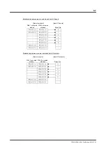
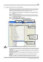
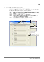
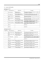
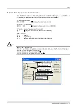
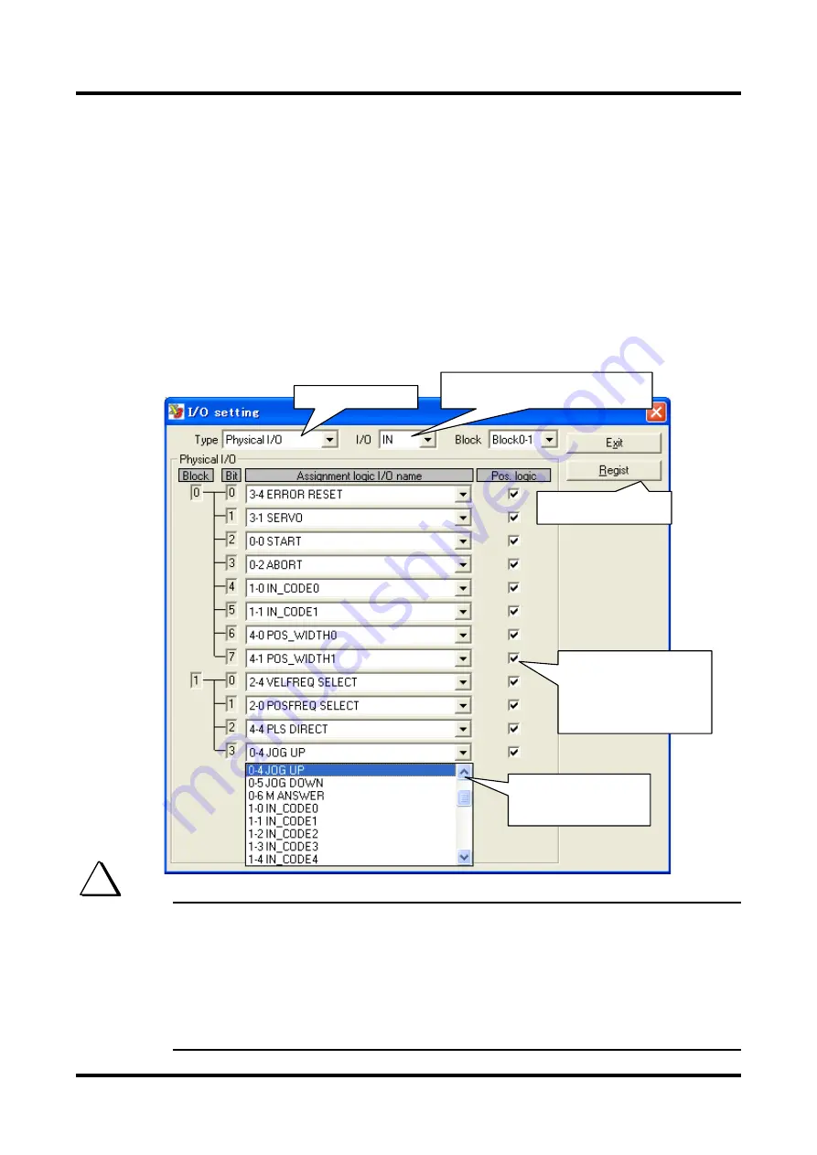
(4) Physical (Hard) I/O Assignment, Logic Setting Method
Follow the procedure below to change the hard I/O assignment. Note that it is not allowed to
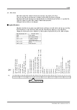
assign the same logic I/O signal to several hard I/O signals. See the next page for the pin
numbers of the controller interface corresponding to each block and bit.
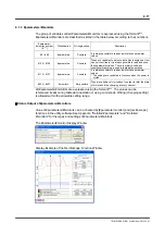
STEP 1 Select [I/O] in Data Management of the utility software to display the I/O Setting
window.
STEP 2 Select [Physical I/O] in Type.
STEP 3 Select [IN] to change I/O inputs in I/O, and select [OUT] to change I/O outputs.
STEP 4 Change an assigned signal in the Assigned Logic I/O Name field corresponding to
the block/bit to be changed.
STEP 5 Change the logic setting as necessary.
STEP 6 Click the [Regist] button to register the settings in the drive.
Note that registration must be performed for each block.
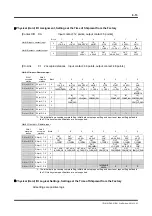
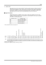
The setting logic and signal status in the contact I/O interface have the following relationship.
<I/O inputs>
Positive logic: The current is conducted into the input photo-coupler when the conditions for
the signal are to be satisfied.
(Example) IN_SERVO: The current is conducted into the photo-coupler to turn the servo ON.
<I/O outputs>
Positive logic: The output transistor switches ON when the conditions for the signal are
satisfied.
(Example) OUT_DRDY: The output transistor switches ON when the drive is ready.
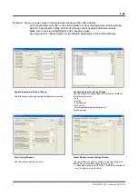
2 Select [Physical I/O].
3 To assign I/O inputs: Select IN
To assign I/O outputs: Select OUT
6 Register the settings in
the drive.
5 Set the logic.
Checked: Positive logic
Unchecked: Negative logic
* Only the OVL signal is set to
negative logic at shipment
from the factory.
4 Change an assigned
signal under the Assigned
Logic I/O Name field.
TIP